
Two-tone electronic doorbell 2
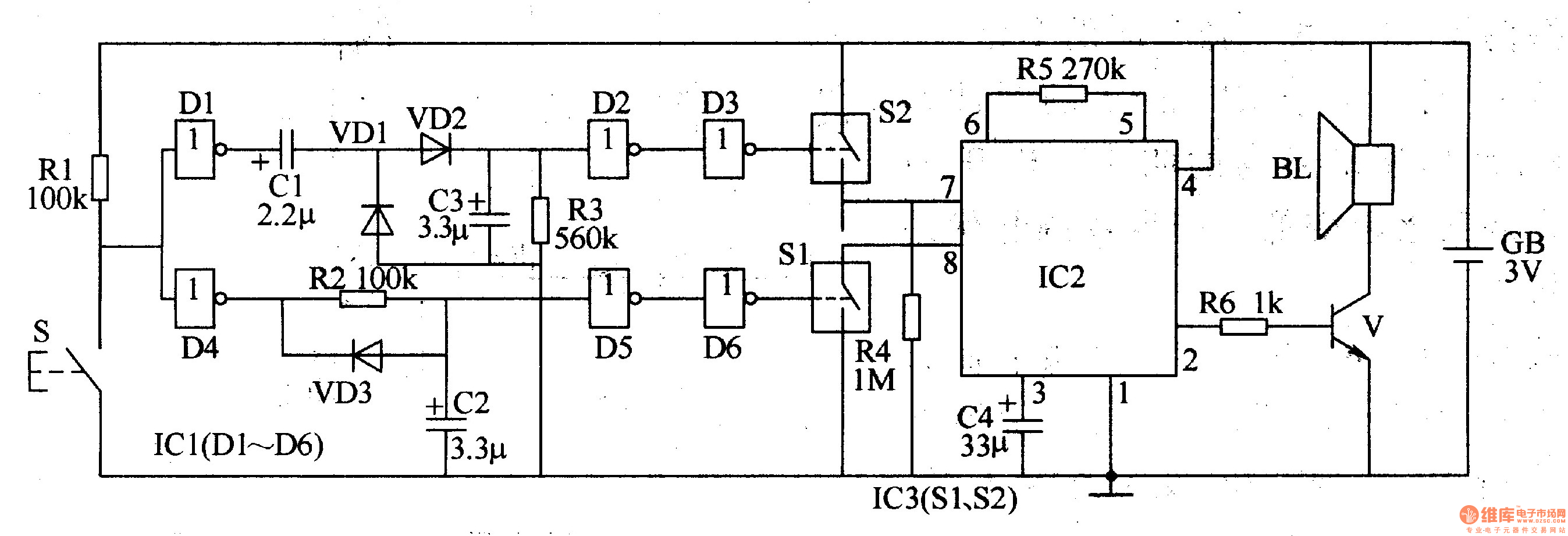
The two-tone electronic doorbell circuit is designed to produce two distinct tones when activated. The trigger control circuit initiates the operation upon pressing the doorbell button (S). This button is connected to a series of resistors (R1-R3) that help manage the current flow and protect the circuit from excessive voltage. The capacitors (C1-C3) serve to filter and stabilize the voltage, ensuring a consistent operation.
Diodes (VD1-VD3) are included in the circuit to prevent reverse polarity and protect sensitive components from potential damage. The six NOT gate integrated circuits (IC1, D1-D6) are configured to generate the two-tone sound by manipulating the input signals from the trigger control circuit. These gates provide the necessary logic to switch between the two tones based on the state of the doorbell button.
The electronic switch (IC3, S1, S2) acts as a relay that connects the doorbell generating circuit to the power supply. When the button is pressed, the trigger control circuit activates the electronic switch, allowing current to flow to the doorbell generating circuit, which produces the audible tones.
Overall, this circuit design effectively combines various electronic components to create a functional and reliable two-tone doorbell system. The integration of logic gates and protective elements ensures durability and performance, making it suitable for residential or commercial applications.The two-tone electronic doorbell circuit is composed of the trigger control circuit and doorbell generating circuit, and it is shown in Figure 3-108. Trigger control circuit consists of doorbell button S, resistors Rl-R3, electrical wear devices Cl-C3, diodes VDl-VD3, six NOT gate integrated circuit ICl (Dl-D6) and the electronic switch IC lC3 (S1, S2).
Door.. 🔗 External reference
Related Circuits
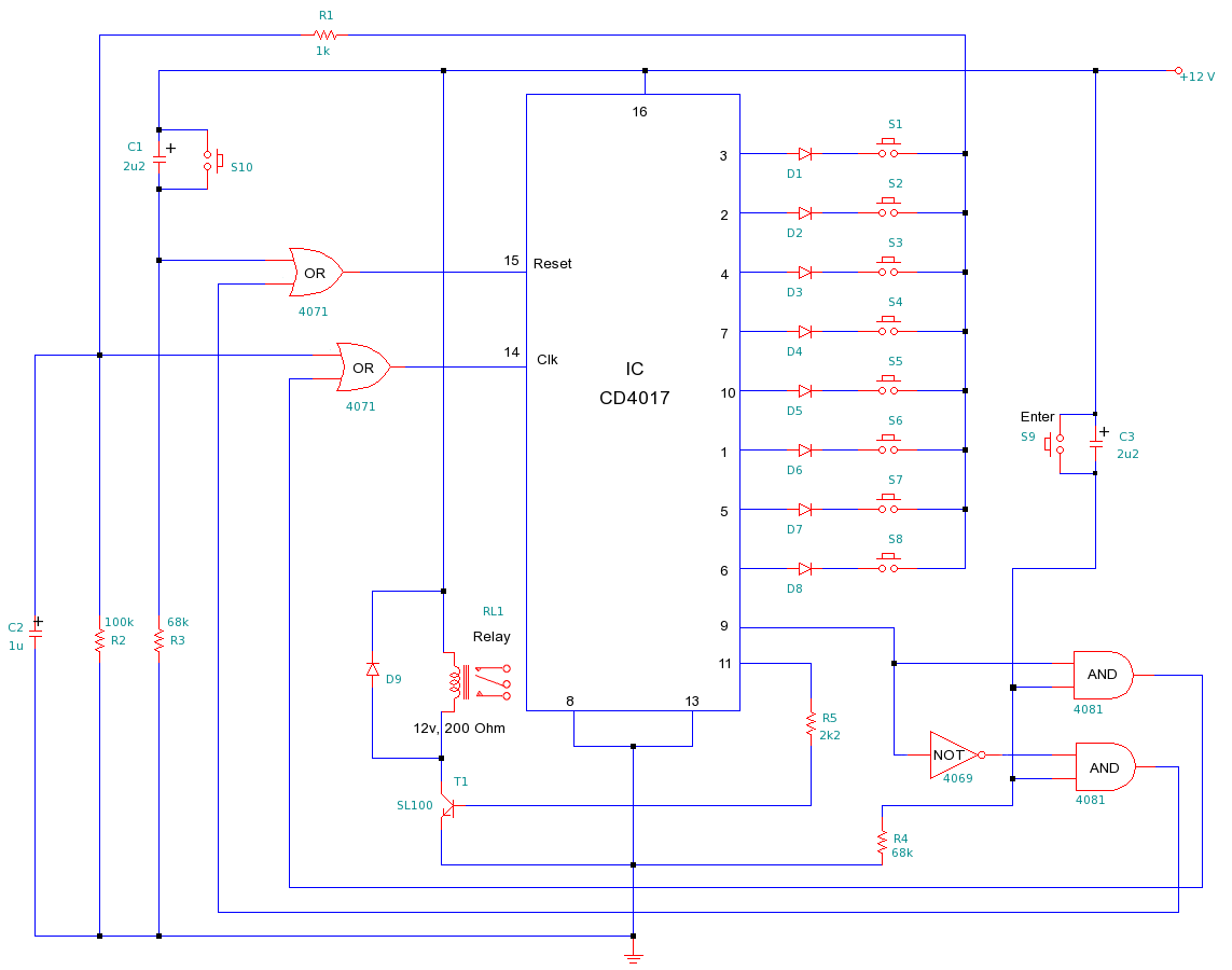
This is a simple yet efficient electronic lock designed to protect electronic systems from unauthorized access. To gain entry, the user must input an 8-digit passcode followed by the "Enter" button. If the correct passcode is entered, the relay...
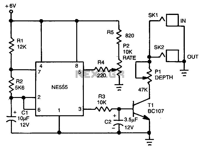
The tremolo effect is created by a repeating change in volume at a frequency typically ranging from 1 to 15 Hz. A timer generates a low-frequency square wave, which is subsequently smoothed by a simple RC integrator. This varying...
The circuit allows up to eight participants, each assigned a unique number from 1 to 8. The display indicates the number of the contestant who presses their button before the others. Simultaneously, a buzzer sounds. Both the display and...
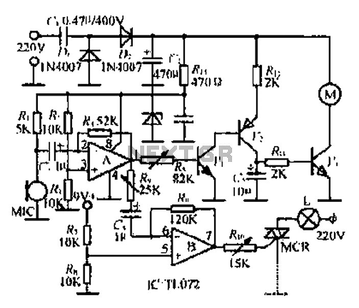
A microphone (MIC) is used to capture sound, which is then converted into a voltage signal. An operational amplifier (op-amp A) acts as a buffer; one output is directed to a motor drive circuit to control the motor's rotation...
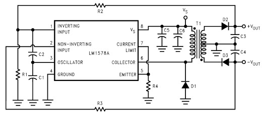
This RS232 power supply circuit diagram is a simple RS-232 line driver power supply that operates from an input voltage as low as 4.2V and delivers an output of ±12V at ±40 mA with an efficiency of better than...

An electronic circuit consists of individual electronic components such as resistors, transistors, capacitors, inductors, and diodes, which are interconnected by conductive wires or traces that allow electric current to flow. The sine wave or sinusoid is a mathematical function...