
Doorbell Memory
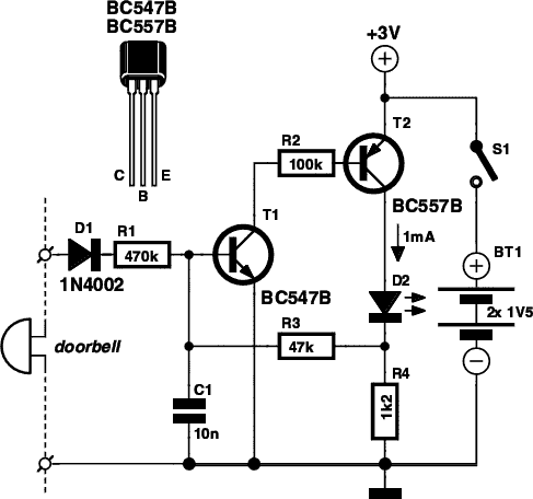
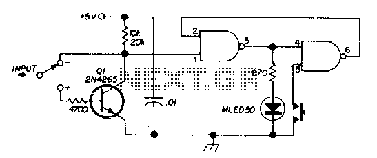
The electronic doorbell memory circuit serves as an efficient solution for individuals who may miss doorbell notifications due to brief absences or distractions. The design incorporates a minimalistic approach, utilizing basic electronic components, which makes it accessible for DIY enthusiasts. The circuit's primary components include a switch, capacitors, transistors, a diode, a resistor, and an LED indicator.
The circuit operates by first charging the capacitor (C1) when the voltage is applied through switch S1. This initial condition ensures that the transistors (T1 and T2) remain off, preventing any current flow to the LED (D2). When the doorbell button is pressed, the diode (D1) allows the AC or DC voltage to pass through, triggering T1. This transistor's activation causes T2 to conduct, illuminating the LED to signal that the doorbell has been pressed.
The design's efficiency is highlighted by the low current draw, which is crucial for battery-operated devices. The use of two 1.5-V penlight batteries in series not only provides the necessary voltage but also ensures longevity in operation. The combination of T2 and resistor R3 creates a feedback loop that keeps T1 conducting even after the button is released, effectively "remembering" the doorbell press until the circuit is reset by opening switch S1.
The circuit's compact nature allows for easy integration into existing doorbell systems, making it a versatile option for various applications. The ability to substitute different transistor types broadens the circuit's adaptability, enabling users to tailor the design to their specific needs. Overall, this electronic doorbell memory circuit presents a practical and efficient solution for enhancing doorbell functionality, ensuring that no visitor is missed due to brief absences or distractions.If you`re expecting an important visitor but you just have to step out for a moment, an electronic doorbell memory can come in handy so you can see whether someone rang while you were out. Of course, you can`t tell whether it was the visitor you were expecting who dropped by then, but a call to the mobile phone of the person concerned can quickly
answer that question. A doorbell memory can also save you the trouble of going to the front door (if you live upstairs) when you think you heard the bell but aren`t sure. And if you can`t buy one, then of course you can build one yourself! Read on to find out how. It takes only a handful of electronic components to build a handy tale-tale with an LED that indicates whether someone pressed the button of your doorbell.
How many times have you thought you heard your doorbell while watching television in the evening The sound of the well-known ding dong` chimes occurs all too often, especially during the many commercials that nowadays remind us at the most inconvenient times that the gripping film we`re watching is only a fantasy. A glance at the LED of the doorbell memory will tell you whether you have to go to the door or can try to escape the ads by zapping to a different channel.
Or if you`re expecting someone but have to make a quick trip to the neighbors to borrow a few beers for the occasion, it can be handy to be able to see whether your visitor already arrived while you were out. If so, you can always call him or her on the mobile to confess that you hadn`t properly prepared for the expected visit.
The circuit is as simple as it is effective. It is connected in parallel with the bell and powered by a 3-V supply formed by two 1. 5-V penlight batteries connected in series. The doorbell memory draws so little current that a set of batteries will last several years in normal use. The circuit works as follows. When the supply voltage is switched on with switch S1, capacitor C1 (initially uncharged) prevents transistors T1 and T2 from conducting.
LED D2 is off, and the memory is armed. When the doorbell button is pressed, the memory circuit receives an AC or DC voltage via diode D1, depending on the type of doorbell. It can handle either type. Transistor T1 thus receives a base current, so it starts conducting and drives T2 into conduction. The LED lights up as an indication that the doorbell has rung (i. e. was energized). The combination of transistor T2 and resistor R3 keeps T1 conducting after the bell voltage goes away (when the button is no longer pressed).
The memory remains in this state until switch S1 is opened. This switch thus acts as a reset switch as well as a power switch. The circuit can be assembled compactly on a small piece of perforated prototyping board, so it can be fitted into just about any model of doorbell. The transistors can be replaced by other, equivalent types as long as you use a combination of NPN and PNP types.
🔗 External reference
Related Circuits
In all the houses exist the bells in the door. All want, they have the possibility of being possible to change the intensity, the tone of sound. With this circuit we have this possibility. With the materials round the...
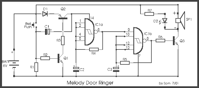
The most challenging aspect of this circuit was determining its title. It can be easy to overlook the sound of a doorbell while watching television; this circuit addresses that issue by providing a visual indication, such as a lamp....
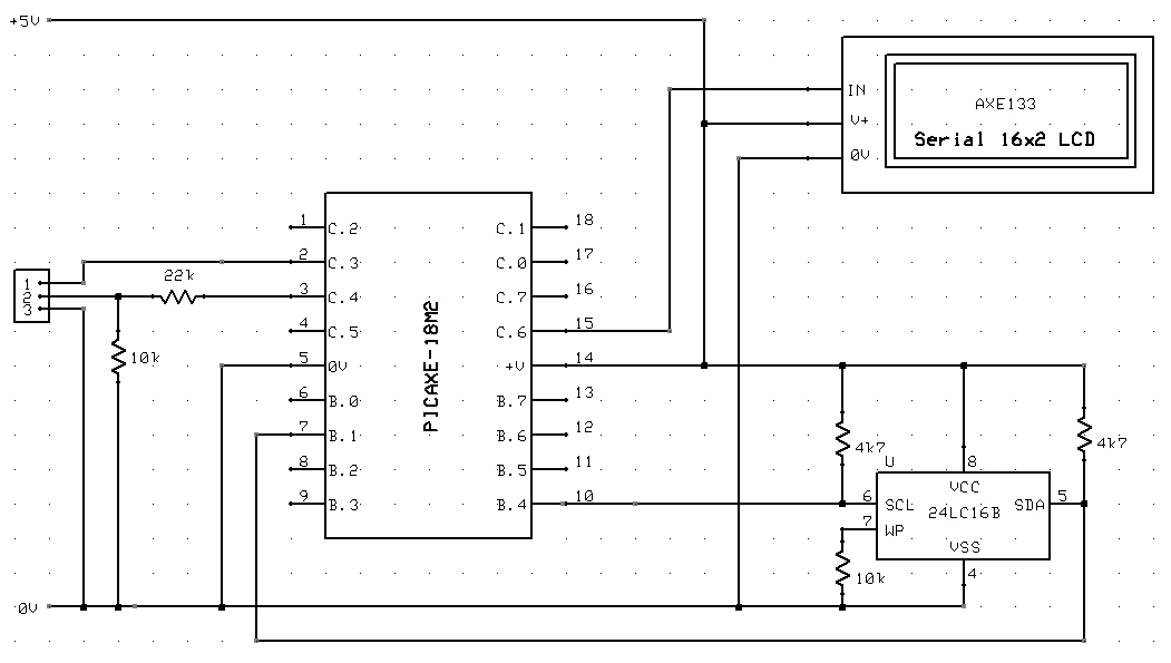
A circuit diagram and sample code is provided to read and write to the 74LC16B memory from a PICAXE microcontroller. The circuit involves interfacing a PICAXE microcontroller with a 74LC16B memory chip, which is a type of EEPROM (Electrically Erasable...
There are two switches: a memory disable switch and a pulse polarity switch. The memory disable switch is a push-button that resets the memory to a low state when pressed. The pulse polarity switch is a toggle switch that...
This circuit detects low-voltage supply conditions, down to 0.6 V. Diode D1 sets the trip point of the circuit. The circuit is useful for protecting memory circuits from accidental writes during low-voltage power supply conditions, which can cause other...
A discussion recently on the mp3projects discussion board about using DRAM memory with small 8-bit processors without DRAM controllers got me to take up an old idea. I thought it should be possible to hook up a DRAM to...