
Remote Doorbell Warning Switchs
This circuit serves the dual purpose of auditory and visual notification of a doorbell press, enhancing the user experience in environments where the doorbell's sound may be masked by other noise, such as television or music. The design incorporates a series resistor (R1) to mitigate the additional load that a parallel lamp or LED would impose on the doorbell's power source. The selection of R1 is critical; it must be calibrated to allow sufficient voltage drop while ensuring that the doorbell mechanism remains operational.
In this configuration, the 22-ohm and 50-ohm resistors are strategically combined to achieve the desired resistance without compromising the doorbell's function. The parallel connection of these resistors effectively lowers the overall resistance seen by the doorbell, which helps maintain its operational integrity while allowing for the visual indicator to illuminate when the doorbell is activated.
The visual indicator, whether a traditional incandescent lamp or a more energy-efficient LED, provides a clear and immediate signal that someone is at the door. This can be particularly beneficial in households with individuals who are hard of hearing or in situations where the doorbell's sound may not be easily heard.
Overall, this circuit design exemplifies a practical solution to a common problem, utilizing basic electronic components to enhance the functionality of a standard doorbell system while considering energy efficiency and user convenience.The hardest part for this circuit was the title. It is quite easy to miss the sound of a doorbell if you are watching TV, this circuit gets round the problem by providing a visual indication, i. e. a lamp. As an alternative, a LED could also be used. You could just parallel a lamp across the doorbell, but this would mean extra drain from the doorb ell batteries or transformer. Using a series resistor R1 actually reduces current flow, and if run from batteries, will give them a longer life. The value of R1 is chosen so that about 0. 6 to 0. 7 volts is dropped across it, and the doorbell should still ring. I used a combination of a 22 ohm resistor in parallel with a 50 ohm. The doorbell still rang and circuit operated correctly. I used to have an electromechanical counter that registered each time when someone pressed the switch.
in fact, I remember a time when I had more "hits" at my doorbell then at my web site=:) 🔗 External reference
Related Circuits
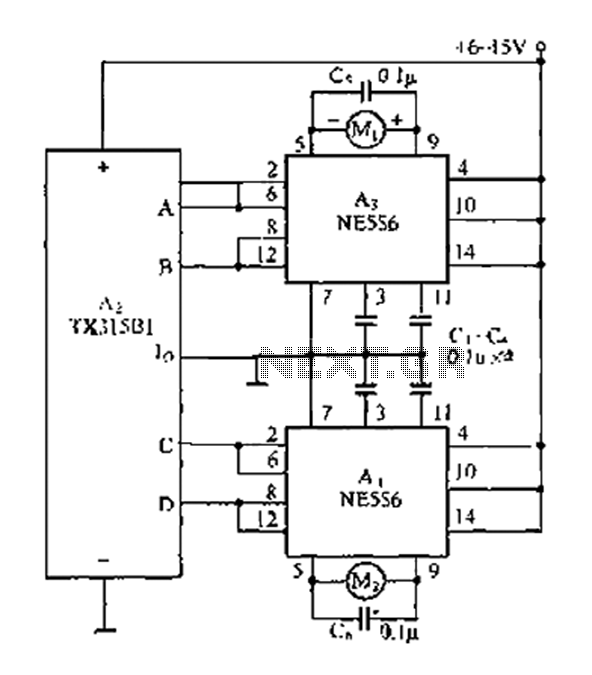
The travel remote control model is represented by a circuit diagram. The NE556 is a dual time base IC that includes two separate circuits, each consisting of a Schmitt trigger circuit. The output control is achieved through the TX315B1,...
Here is a handy gadget for testing of infrared (IR) based remote control transmitters used for TVs and VCRs etc. The IR signals from a remote control transmitter are sensed by the IR sensor module in the tester and...
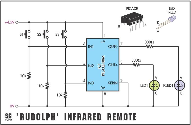
To send the Sony command "TV - mute," the command would be infraout 1, 20. Note that the device should always be 1 when used in PICAXE projects, and data can only be between 0 and 127, as the...
The DTMF infrared remote control circuit utilizes a DTMF encoded signal that can be decoded by a specialized decoder and the PLL audio decoder LM567. However, a DTMF encoded signal decoded by a single decoder yields only one frequency....
Circuit of a new type of remote control switch is described here. This circuit functions with inaudible (ultrasonic) sound. Sound of frequency up to 20 kHz is audible to human beings. The sound of frequency above 20 kHz is...
While developing an infrared (IR) extender circuit, a method was needed to measure the relative intensities of various infrared light sources. This circuit is the outcome of that research. A photodiode, specifically the SFH2030, is utilized as the infrared...
Warning: include(partials/cookie-banner.php): Failed to open stream: Permission denied in /var/www/html/nextgr/view-circuit.php on line 713
Warning: include(): Failed opening 'partials/cookie-banner.php' for inclusion (include_path='.:/usr/share/php') in /var/www/html/nextgr/view-circuit.php on line 713