
Doppler Rdf

The circuit design incorporates a 7812 voltage regulator, which provides a stable 12V output that is then stepped down to 6V through an operational amplifier configured for this purpose. This ensures that the audio stages receive a reliable midpoint voltage, crucial for optimal performance in battery-operated scenarios. The use of an integrator configuration for the op-amps allows for the smoothing of signals, minimizing abrupt changes that could lead to instability in the output.
The biasing network of two resistors is strategically placed to set the correct voltage levels at the positive inputs of the op-amps. This biasing is vital as it directly influences the output waveforms, ensuring that transitions between antenna states occur smoothly and without distortion. The design addresses the common issue seen in previous iterations where low input signals resulted in unstable readings and high signals caused clipping, which could severely impact the accuracy of the system.
The integration of automatic gain control (AGC) enhances the system's ability to maintain a consistent output despite varying input levels. This feature is particularly beneficial in filtering out noise while preserving the integrity of signals that are close to the target frequency. The capacitors in the circuit play a critical role in this process by adapting to the voltage levels over time, allowing for only significant deviations to be adjusted, thus maintaining the overall stability of the audio output.
Furthermore, the connection of the NAND gate output to the dimmer transistor via a 3.3kΩ resistor introduces Schmitt-trigger behavior, which is essential for providing a clean transition during the "freeze" state of the bearing. This mechanism ensures that fluctuations in the AGC voltage do not inadvertently trigger the retriggering of the 40174, thus preserving the accuracy of the readings. The adjustment of sensitivity is a user-friendly feature, allowing for fine-tuning without the need for complex recalibrations, simply by manipulating the sensitivity control until the desired "freeze" effect is achieved.
Overall, this circuitry design emphasizes stability, adaptability, and user-friendliness, making it suitable for applications requiring precise audio signal processing and reliable performance in varying conditions.The power supply is just a 7812 voltage regulator followed by an op-amp set to 6V to create a half way supply voltage for the audio op-amp stages. A 12V regulator seems to be too high for a battery fed application. These 4 outputs are all followed by a op-amp set up as an integrator. and the R/C circuitry around these op-amps ensure a very soft transition to the next antenna element. A network of two resistors feeding the + inputs of the op-amps is used to bias the op-amps; the voltage on the + inputs is determining the output waveforms and therefore the resulting transition from one to the next antenna. This is quite important for normal operation; in existing designs very small input signals will not give a stable reading, and signals that are too big will clip in the last filter stages resulting in serious bearing deviations.
Therefore, the automatic gain control in the PA8W Doppler is a valuable addition. That means that a constant audio signal exactly on frequency will hardly be affected by the capacitors that will already have been charged to the right voltage over some time. Only parts in the audio that deviate from average will be reduced extremely because the capacitors will have to be charged or discharged to the new value.
All kinds of parameters, such as group delay in your receiver and phase shift in the RDF low pass filter stages will shift this point away from the truth, The output of the NAND poort should be connected via the 3M3 resistor to the base of the dimmer transistor to provide some schmitt-trigger action for a clean "freeze" of the last bearing. As soon as the AGC voltage is dropping below the "freezing point" the collector of the dimmer transistor will go up and the output of the NAND will go down, preventing the 40174 to be retriggered.
A simple way to adjust it correctly is by turning sensitivity fully clockwise (with no input signal!) and then slowly turning it counterclockwise until the pelorus freezes. 🔗 External reference
Related Circuits

The relative motion between a satellite and an observer causes a frequency shift known as the Doppler effect. Doppler is well-understood and can be corrected automatically by satellite tracking software. The Doppler effect is a phenomenon observed in various fields,...
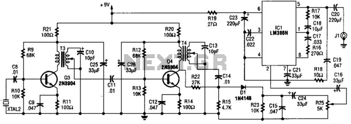
XTAL1 drives amplifier Q3/Q4, which is tuned to 2.25 MHz. The detected signal is fed to audio amplifier IC1. A 9-V supply is used. The circuit operates at 2.25 MHz and is designed to be used with an ultrasonic...
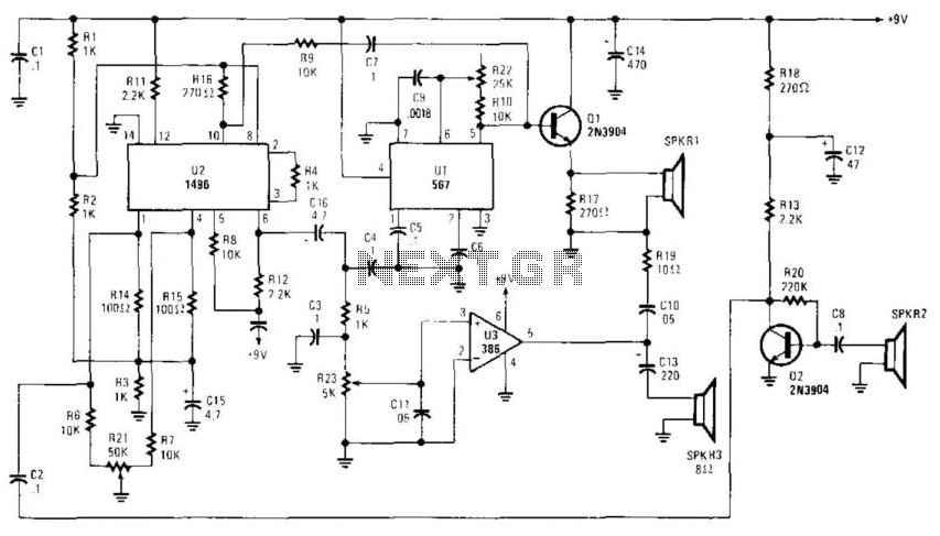
A high-frequency audio signal (15 to 25 kHz) generated by Ul is fed to buffer Ql and SPKR1. A portion is fed to balanced mixer U2. Received audio picked up by SPKR2 (used as a microphone) is amplified by...
The UHF motion detector operates on the Doppler radar principle. An oscillating signal is generated by the oscillator (Q1), and a portion of this energy is reflected back. The UHF motion detector employs the Doppler radar principle to detect motion...
Doppler units are widely used by mobile T-hunters across various regions, serving as effective tools for indicating the direction of incoming VHF signals via a circular arrangement of light-emitting diodes or a digital display. These units can update bearings...
The 2.25-MHz oscillator Q1 drives amplifier Q2 and XTAL1, an ultrasonic transducer. The transducer is a lead zirconate-titanate type. Taps on T1 and T2 provide low-impedance drive points. The circuit consists of a 2.25-MHz oscillator (Q1) that serves as the...