
UHF Doppler Motion Detector

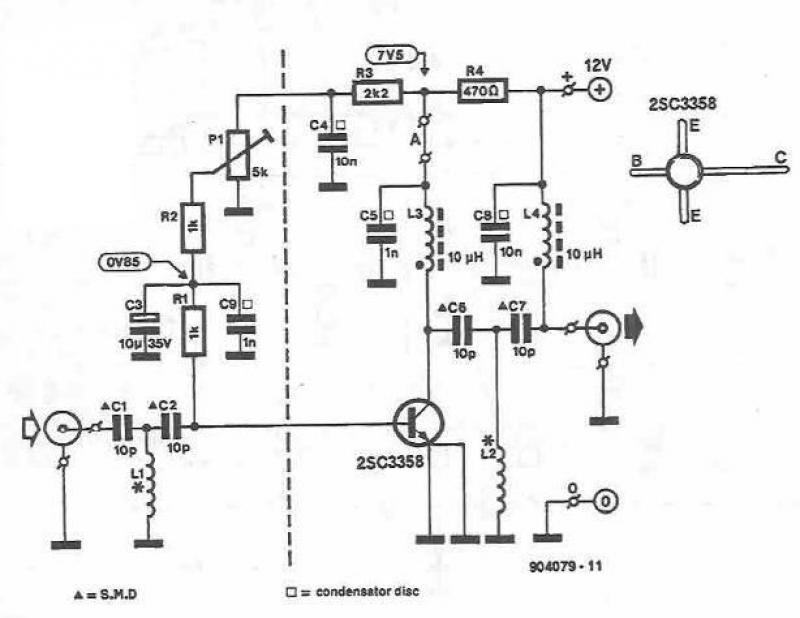
The UHF motion detector employs the Doppler radar principle to detect motion through the analysis of frequency shifts in reflected signals. The oscillator (Q1) generates a continuous wave signal at UHF frequencies, typically within the 300 MHz to 3 GHz range. This signal propagates through the environment, and when it encounters a moving object, the frequency of the reflected signal is altered due to the Doppler effect.
The circuit configuration includes essential components such as amplifiers, mixers, and filters to process the reflected signals. The received signal is mixed with the original transmitted signal to produce an intermediate frequency (IF) signal, which is easier to analyze. This IF signal is then amplified and filtered to remove noise and enhance the detection of motion.
The output from the detector can be used to trigger alarms, activate lighting systems, or interface with other security systems. The sensitivity of the motion detector can be adjusted by modifying the gain settings of the amplifiers and the threshold levels in the processing circuitry. Additionally, the design may incorporate a microcontroller or digital signal processor (DSP) to enhance functionality, allowing for programmable detection parameters and integration with smart home systems.
Overall, the UHF motion detector represents a sophisticated application of radar technology, providing reliable motion detection capabilities in various environments.The UHF motion detector below operates on the Doppler radar principle. A radial signal is created by the oscillator (Q1). Some of this energy is reflected back.. 🔗 External reference
Related Circuits

This simple circuit is designed to detect RF radiation leakage from transmitters, faulty connections, broken cables, or equipment with inadequate RF shielding. It is specifically tailored for the 2-meter amateur radio band (144-146 MHz in Europe). The device features...
This UHF amplifier circuit project is beneficial for enhancing weak TV signals. The amplifier provides a gain of 10-15 dB within a frequency range of 400 to 850 MHz. To ensure optimal performance and reliability, the PCB tracks should...
This circuit illustrates a Lie Detector Circuit Diagram. It is based on the principle that a person's skin resistance varies when they experience emotional stress. The Lie Detector Circuit operates on the principle of galvanic skin response (GSR), which measures...
A bright lamp flashes in synchrony with the lightning bolts, indicating the proximity and intensity of the storm. The described circuit operates as a storm warning system, utilizing a bright lamp to provide visual alerts in response to lightning activity....
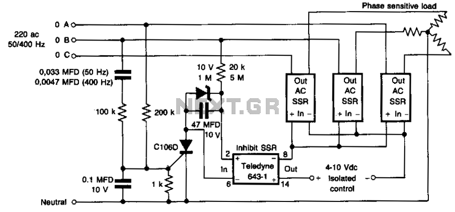
This circuit prevents damage to the load due to incorrect phasing. The three power solid-state relays (SSRs) are only permitted to turn on for a phase sequence where phase A leads phase B. If phase A lags phase B,...
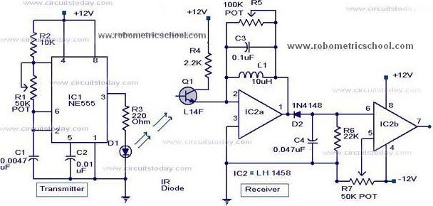
All components used in the Moving Sensor/Detector Schematic Diagram utilize the IC NE555 and the Phototransistor L14F. The primary component in this circuit is the IC NE555, along with an IR LED, the Phototransistor L14F, and the IC LM1458....