
Wide-Range Doppler Antenna

The Roanoke Doppler system employs a sophisticated yet user-friendly design that enhances the capabilities of amateur radio operators engaged in transmitter hunting. The core of the system is the multi-element antenna assembly, which optimally captures VHF signals. The control unit plays a crucial role by processing the audio output from the transceiver or scanner, allowing for real-time direction finding. The integration of the light-emitting diodes or digital display provides immediate visual feedback, enabling users to make swift adjustments and track signals effectively.
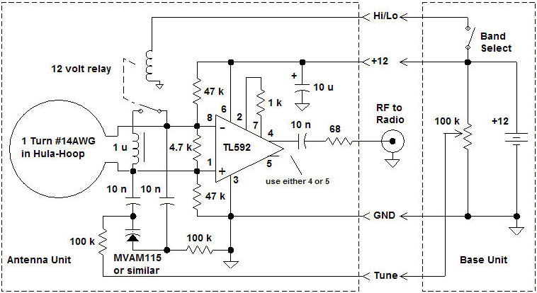
The antenna array's design, featuring four quarter-wavelength whips, is strategically arranged to maximize signal reception while minimizing interference. The inclusion of a metal plate and radials creates an effective ground plane, which is essential for enhancing the performance of the whips. The introduction of the improved switching system with PIN diodes represents a significant advancement, as it allows for flexibility in coax lengths, thus broadening the operational bandwidth of the system. This flexibility is particularly beneficial for users who may wish to operate across various frequency bands without the need for multiple antenna setups.
The schematic diagram of the new wideband switcher illustrates the innovative design approach, highlighting the importance of feedpoint impedance control and impedance matching at the common point. This attention to detail ensures optimal performance and reliability, which are critical in the competitive environment of T-hunting. The Roanoke Doppler's design not only emphasizes functionality but also encourages the spirit of homebrew construction among amateur radio enthusiasts, fostering a community dedicated to innovation and practical application in radio direction finding.Doppler units are the "weapon of choice" among mobile T-hunters in many parts of the country. They indicate the direction of incoming VHF signals on a circular ring of light-emitting diodes or a digital display. A doppler set updates bearings almost instantaneously, so even short carrier bursts can be tracked. A doppler installation can be done quickly on just about any vehicle. It has a much lower profile than a RDF yagi or quad setup. The multi-element antenna assembly replaces your mobile whip. The control unit extracts direction information from a tone that the antenna set adds to the audio output of your VHF-FM transceiver or scanner. Excellent commercial doppler models are available for several hundred dollars, but you can build your own at a fraction of the cost.
Today`s most popular do-it-yourself doppler was originated by Chuck Tavaris N4FQ of Roanoke, Virginia. Tom Curlee WB6UZZ and I made enhancements and documented the design. We named it the Roanoke Doppler in honor of N4FQ`s T-hunting grounds. Complete plans for the Roanoke Doppler are in "Transmitter Hunting-Radio Direction Finding Simplified" by Moell and Curlee.
One chapter in this book thoroughly discusses the theory of RDF using the doppler principle and gives much more information about techniques, advantages and disadvantages than space here allows. The Roanoke Doppler has been built by hundreds of hams in many forms (see Photos 1 and 2 below). Several independent suppliers have made circuit boards and kits available for its controls and display.
They are not affiliated with the book`s authors or publisher, so contact them directly for information on their products. Photo 1 (left). This Roanoke Doppler display box was built by Jerry Boyd WB8WFK of Albuquerque, NM. Note the 10-turn potentiometer and large dial for the calibration control. This allows him to log settings for each band. (Photo by WB8WFK) Photo 2 (right). The Roanoke Doppler display circuits are designed for easy "homebrew" construction. Bill Briles WG OQC of Derby, KS built his on perforated prototyping board. Etched circuit boards are also available from several sources. (Photos by WG OQC) The Roanoke Doppler antenna design in the book (see Photo 3 below) works well on strong two meter signals.
I have used it on well over a hundred T-hunts. But it has room for improvement. The requirement for exact half-wavelengths of coax limits an array to a narrow frequency range (typically 5%). Furthermore, readers who have tried to scale the array for higher frequencies (such as the 70 centimeter band) have had disappointing results.
Photo 3. The Roanoke Doppler antenna array described in TRANSMITTER HUNTING has four quarter-wavelength whips on a 20 X 20 inch metal plate with 8 radials to provide a ground plane under each whip. In 1994, I designed an improved switching system for the Roanoke Doppler and invited several T-hunters to build and test it.
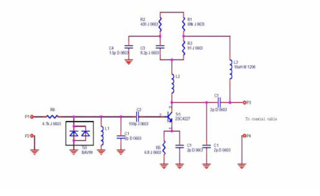
The new design (schematic in Figure 1 below) features series PIN diodes at each end of the coax lines to the four whips. This means that the coaxes can be any reasonable length, so long as the four lengths are equal. Coax lengths no longer limit the bandwidth of the array, so it is possible to use one array to cover tens of megahertz, limited only by array spacing and values of inductors and capacitors in the switcher.
(Why is it important to have diodes at each end of each coax See Homing In for April 1995, which explains in detail the importance of controlling both the feedpoint impedance of switched-off whips and the impedance match at the common point. ) Figure 1. Schematic diagram of the new wideband switcher for the Roanoke Doppler. The P-in-a-triangle symbol denotes a connection to the ground plane sheet of the one-piece version. For the mag-mount version, the P-in-a-triangle points at the whip ends of the coaxes are connected to the magnets but remain insulated from the car body.
Compon 🔗 External reference
Related Circuits
Homemade antennas can significantly enhance the performance of AM and FM radios, short-wave receivers, and scanners. For enthusiasts of talk radio, experimenting with AM band antennas can lead to the ability to receive broadcasts from across the country with...

This is a design circuit for a low-cost FM antenna booster that can be used to listen to programs from distant FM stations clearly. The antenna FM booster circuit comprises a common-emitter tuned RF preamplifier wired around the VHF/UHF...
A CD4046 can be gated either with a switch or electronically, as shown in the figure. The frequency range of this circuit is up to 1.5 kHz; use another capacitor C1 for higher frequencies. The CD4046 is a versatile phase-locked...
This circuit extracts the synchronization pulses from a video signal across a wide range of amplitudes and operates on a single +15 V supply. IC1 buffers and amplifies the incoming signal and applies it via C3 to the peak...
This circuit is designed to amplify the input from a telescopic whip antenna. The preamplifier is intended to operate within the medium waveband, covering frequencies from approximately 550 kHz to 1650 kHz. The required tuning voltage ranges from 1...
A flat mobile active car antenna is being tested with a Terratec Cinergy DT USB XS Diversity digital tuner. The antenna is designed to enhance signal reception for mobile digital television. The flat mobile active car antenna is engineered to...