
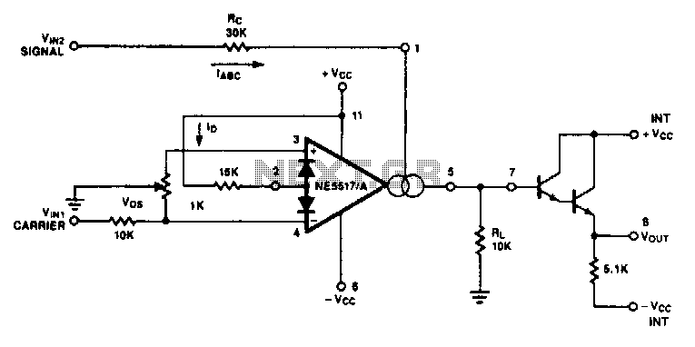
Double-Sideband Suppressed-Carrier (DSB-SC) Modulator
 Modulator")
In amplitude modulation (AM), the carrier signal's amplitude is varied in accordance with the modulating signal. This process results in the generation of sidebands that carry the information of the modulating signal. The DSB-SC technique is particularly notable as it effectively removes the carrier component, which is not necessary for the demodulation process, thereby improving power efficiency during transmission.
The modulation process can be visualized in a schematic that typically includes components such as operational amplifiers, resistors, and capacitors configured to create the desired modulation effect. The operational amplifiers serve as the primary means of manipulating the amplitude of the carrier signal based on the input from the modulating signal. The differential pairs are critical in managing the balance between the carrier and modulating signals, ensuring that the output remains clean and devoid of the carrier frequency.
The frequency analysis of the output signal can be performed using a spectrum analyzer, which will show the two sidebands and confirm the absence of the carrier frequency. This capability allows for efficient use of bandwidth and power in communication systems, making DSB-SC modulation a preferred choice in various applications, including broadcast radio and data transmission. The careful design of the circuit components and their configurations is essential for achieving the desired modulation characteristics while maintaining signal integrity.When we modulate a carrier signal with amplitude modulation, there will be four frequency components as the result. The first is the modulating signal itself, the second is the frequency carrier, the the latest two are the difference and the sum of the carrier and the modulating signal.
The spectrum of these frequencies can be seen using frequenc y analyzer. In radio transmission, the modulating frequency components is completely filtered out since the frequency is far lower than the other three. To increase the power efficiency, double sideband suppressed carrier modulator (DSB-SC) remove the carrier frequency part, so the transmitted frequencies consist only the side bands: the sum and the difference.
In the schematic diagram below, a double-sideband suppressed-carrier modulator circuit is presented. There is no carrier appear in the output because of the basic current. The Carrier amount appear in at the output can be controlled by adding offsets to the carrier differential pairs. The function of the modulation signal-AM modulation is the amplitude. 🔗 External reference
Related Circuits
The transconductance of an operational transconductance amplifier is directly proportional to the transconductance parameter, allowing for easy control of signal amplification. The output current is calculated as the product of transconductance and input voltage. This circuit operates effectively up...
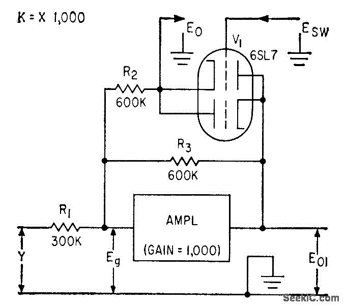
This circuit is utilized in a multiplier that operates with one of the operational amplifiers in an analog computer. The double-triode V1 in this configuration provides pulse-amplitude modulation, which is intended for use with a separate pulse-width modulator to...
The circuit schematic of the UDC consists solely of dispersive components. Two low-frequency series LC resonators, with equal inductances (LA=LB) and capacitances (CA=CB), are connected to two input semi-infinite transmission lines, designated as A and B. These resonators are...
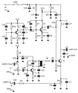
This is the circuit diagram of an audio/video modulator. The circuit converts audio and video signals into a UHF TV signal, allowing a video signal from a camera or other source to be connected to a standard TV set....
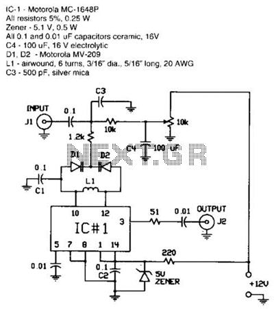
The FM modulator is constructed using a Motorola MC1648P oscillator. Two varactors, the Motorola MV-209, are employed to frequency modulate the oscillator. A 5000-ohm potentiometer is utilized to bias the varactors for optimal linearity. The output frequency, which is...
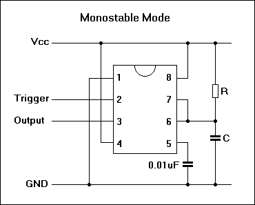
In the 555 datasheet, there is a pulse width modulation circuit that resembles this one, with the only difference being that pin 5 is labeled as 'audio'. The 555 timer IC is a versatile device commonly used in various applications,...