
Modulator

The operational transconductance amplifier (OTA) is a versatile component widely used in analog signal processing. It operates by converting an input voltage into an output current, which is proportional to the transconductance (gm) of the device. The transconductance can be adjusted by varying the biasing conditions, enabling precise control over the amplification of signals.
In practical applications, the OTA can be configured in various circuit topologies, such as integrators, differentiators, and voltage-controlled amplifiers. The ability to achieve a modulation depth of 99% indicates the OTA's effectiveness in applications such as amplitude modulation and signal mixing, where high fidelity and dynamic range are essential.
The frequency response of the OTA is crucial, with effective operation up to 200 kHz, making it suitable for audio and communication systems. Careful consideration of the circuit layout, component selection, and power supply decoupling is necessary to maintain performance at higher frequencies and to minimize distortion.
For applications requiring specific transconductance values, external resistors or current sources can be employed to set the gain accurately. The OTA can also be integrated into more complex systems, such as filters and oscillators, where its transconductance characteristics can be exploited to achieve desired frequency responses and signal behaviors.
In summary, the operational transconductance amplifier offers a flexible and efficient means of signal amplification and modulation, with applications spanning a wide range of electronic systems, particularly where precision and control are paramount.Because the transconductance of an operational transconductance amplifier is directly proportionai to /ABc. the amplification of a signal can be controlled easily. The output current is the product from transconductance X input voltage. The circuit is effective up to approximately 200kHz. Modulation of 99% is easy to achieve.
Related Circuits

If you have considered experimenting with pulse-width modulation, this circuit serves as an excellent starting point. Simplicity has been prioritized in the design, utilizing a dual... This circuit is designed to facilitate experimentation with pulse-width modulation (PWM), a technique widely...
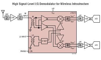
The LT5575 is an 800MHz to 2.7GHz direct conversion quadrature demodulator optimized for high linearity receiver applications. It is suitable for communications receivers where an RF signal is directly converted into I and Q baseband signals with a bandwidth...
The Pulse Demodulator, as illustrated in the accompanying image, consists of a CMOS Hex Inverter. This circuit is capable of performing envelope detection on amplitude pulses. The Pulse Demodulator utilizing a CMOS Hex Inverter is designed to extract the envelope...
The following is a translation of a section from the first book of the three-part series "Die Röhre im UKW Empfang" edited by Dr. Ing. Horst Rothe in 1952. This section describes a fully differential super-regenerative self-limiting FM detector....
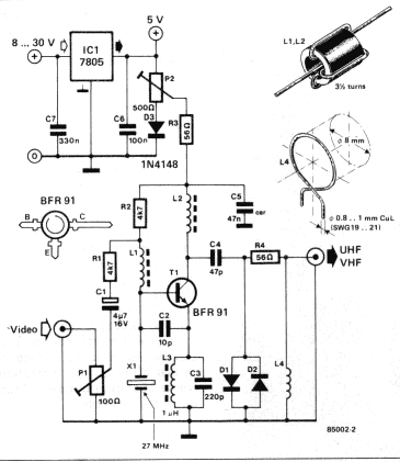
A TV modulator is really no more than a transmitter. It is a very small transmitter, admittedly, but none the less that is what it is. What does a modulator actually do? In general - and this design is...
Replacing the LC modulation circuit with an active filter allows for the elimination of large and costly inductance coils in frequency shift key control demodulators. This approach not only reduces the size of the circuit but also enhances the...