
550 to 1100 KHz AM Receiver Circuit

The AM receiver circuit designed for the frequency range of 550 to 1100 KHz typically consists of several key components that work together to demodulate amplitude-modulated signals. The primary components include an antenna, a radio frequency (RF) amplifier, a mixer, a local oscillator, a demodulator, and an audio amplifier.
The antenna captures the incoming radio waves, converting them into electrical signals. These signals are then fed into the RF amplifier, which amplifies the weak signals to a level suitable for further processing. The RF amplifier may employ transistors or operational amplifiers to enhance the signal strength while minimizing noise.
Following amplification, the signals are mixed with a local oscillator signal in the mixer stage. The local oscillator generates a frequency that allows the desired signal to be down-converted to an intermediate frequency (IF), typically around 455 KHz for AM receivers. This process enables better filtering and amplification of the desired signal while rejecting unwanted frequencies.
The demodulator then extracts the audio information from the modulated carrier wave. This can be accomplished using various techniques, such as envelope detection or synchronous detection. Envelope detection is the most common method used in simple AM receivers, where the amplitude variations of the incoming signal are directly translated into audio signals.
After demodulation, the audio signal is often weak and requires further amplification. An audio amplifier is employed to boost the audio signal to a level suitable for driving speakers or headphones. This stage may include additional filtering to enhance sound quality and remove any remaining high-frequency components.
To enhance the performance of the AM receiver, components such as variable capacitors and inductors may be included to allow for tuning and adjustment of sensitivity and selectivity. These adjustments enable the user to optimize the circuit for specific stations and improve overall reception quality.
In summary, the AM receiver circuit operating between 550 and 1100 KHz is a complex assembly of components that work together to receive, amplify, demodulate, and output audio signals from amplitude-modulated radio transmissions. The ability to adjust sensitivity and selectivity is crucial for effective operation in varying radio environments.The following circuit shows about 550 to 1100 KHz AM Receiver Circuit. Features: used to adjust the sensitivity and selectivity of the circuit, .. 🔗 External reference
Related Circuits
The refrigerator turned on, causing the lights to brighten. Initially, it seemed like an illusion, but after observing multiple cycles, the phenomenon persisted. When the microwave was activated, the lights dimmed. The refrigerator's operation appeared to influence the brightness...
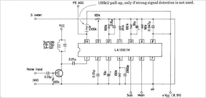
The LA1070 is an automatic gain control integrated circuit designed for use with automotive on-glass antennas. It is produced by Sanyo Semiconductor Corporation. The LA1070 operates by automatically adjusting the gain of the antenna signal to maintain a consistent output...
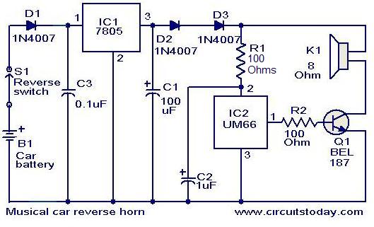
This circuit is designed to produce a musical horn whenever a car is in reverse gear. It utilizes two integrated circuits (ICs) for its operation: a voltage regulator (7805, referred to as IC1) and a musical tone generator (UM66,...
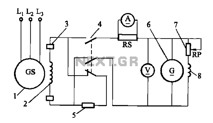
Adjust the exciter field rheostat RP to change the exciter output voltage, which in turn adjusts the generator excitation current, allowing for modifications to the generator output voltage for various purposes. The exciter field rheostat (RP) is a critical...
The infrared receiver requires the infrared light to be modulated at 38 kHz, which corresponds to a period of 26 µs. The specifications for the receiver suggested using a 50% duty cycle; however, this configuration did not perform as...
Asia ultrasonic remote control switch. This example describes the use of a gas pressure bisulfite ultrasound flute (made of rubber, available in olive and flat round shapes) for control. When the ultrasonic flute is activated, the remote control switch...