
Photo Detector Circuits
The described photo-detector circuits are designed to detect the presence of trains by utilizing visible light sensors, typically phototransistors or photodiodes. These sensors are strategically mounted between the rails to monitor the light conditions in their vicinity. When a train passes over the sensor, it interrupts the light path, triggering a response in the circuit.
A basic circuit configuration may include a phototransistor connected in a voltage divider arrangement with a resistor. The phototransistor is sensitive to changes in light intensity; thus, when the light is interrupted by a train, the change in current flow through the phototransistor alters the voltage across the resistor. This voltage change can be fed into a microcontroller or an operational amplifier to produce a digital signal indicating the presence of a train.
In addition to the basic detection functionality, these circuits can be enhanced with features such as hysteresis to prevent false triggering due to transient light changes, and debounce circuits to manage the signal stability when the train is approaching or leaving the detection zone. The output can be configured to activate alarms, lights, or other signaling mechanisms to alert personnel of an approaching train.
Power supply considerations are essential, as these circuits may be powered by low-voltage sources, typically ranging from 5V to 12V, ensuring safe operation and compatibility with other system components. Proper housing and weatherproofing of the sensors are also crucial for outdoor applications to maintain reliability and longevity in varying environmental conditions.
Overall, the implementation of visible light photo-detector circuits for train detection presents a reliable solution for enhancing safety and operational efficiency at railway crossings and monitoring systems.This page features basic, visible light photo-detector circuits that can be used to detect trains. These methods would normally be used with the photo sensor mounted between the rails. 🔗 External reference
Related Circuits
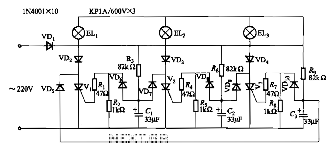
The circuit operates with a 220V mains supply through a diode (VDi) configured as a half-wave rectifier. Capacitors C1 to C3 are charged, and due to the lack of full synchronization in the charging process, a pilot thyristor is...
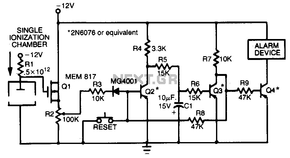
This smoke detector employs a MEM 817 p-channel enhancement mode MOSFET as its buffer amplifier. The sensor operates on the principle that the current decreases when smoke enters the chamber, leading to a negative voltage change at the gate...
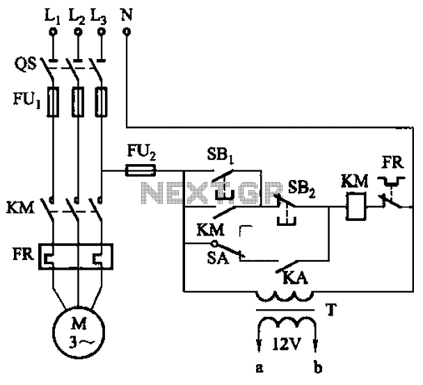
The circuit illustrated in Figure 3-81 employs a transistor delay circuit to facilitate start-stop cycle control. It can operate in both manual and automatic modes. The circuit is primarily governed by the motor run time circuit, which includes transistors...
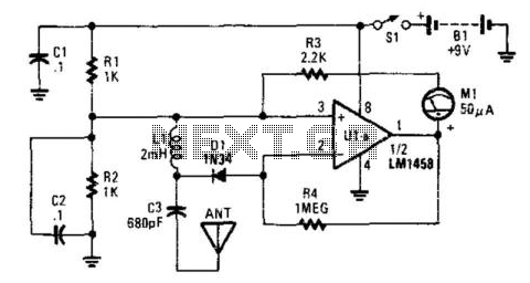
This detector is a half-wave rectifier for RF, which then feeds an operational amplifier. U1A acts as an amplifier, driving meter M1. This circuit can detect milliwatt RF levels from below the AM broadcast band to well above the...
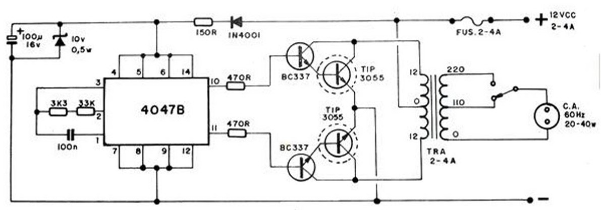
The converter transforms 12 VDC to 220 VAC, allowing for the conversion of 12 volts DC into 220 volts AC. The circuit diagram provided illustrates a simple converter circuit. This DC to AC converter can supply voltage for a...
This circuit can be used as an infrared beam barrier as well as a proximity detector. The circuit uses the very popular Sharp IR module (Vishay module can also be used). The pin numbers shown in the circuit are...