
drinking water alarm schematics
This water alarm circuit is designed to provide users with an audible alert when the water supply resumes, enhancing the convenience of water usage in areas with intermittent supply. The heart of the circuit relies on the 555 timer IC, which is utilized in astable mode to generate a continuous square wave signal. The frequency of oscillation, set to approximately 1 kHz, is sufficient to drive a small loudspeaker, ensuring the alert is noticeable.
The water sensor, constructed from aluminum and plastic foils, acts as a conductive element that completes the circuit when water flows through it. This innovative design allows for a seamless integration into existing water taps without requiring extensive modifications. The use of a resistor (R2) in the circuit helps to limit current and protect the timer IC from potential damage, ensuring longevity and reliability.
The circuit's components should be carefully selected to ensure compatibility and optimal performance. Capacitor C3 plays a crucial role in coupling the output signal from the 555 timer to the loudspeaker, filtering any DC components and allowing only the AC signal to pass through, which produces sound. The on/off switch (S1) provides an easy way to deactivate the circuit when not in use, conserving battery life.
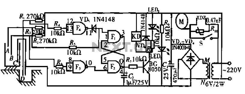
For assembly, a general-purpose PCB is recommended to allow for organized placement of components and ease of soldering. Housing the circuit in a suitable cabinet will protect it from environmental factors and mechanical damage, ensuring consistent operation. The overall design is compact and efficient, making it suitable for various domestic and commercial applications where water supply is unpredictable.The State Jal Boards supply water for limited duration in a day. Time of water supply is decided by the management and the public does not know the same. In such a situation, this water alarm circuit will save the people from long wait as it will inform them as soon as the water supply starts. At the heart of this circuit is a small water sensor. For fabricating this water sensor, you need two foils ”an aluminium foil and a plastic foil. You can assemble the sensor by rolling aluminium and plastic foils in the shape of a concentric cylinder. Connect one end of the insulated flexible wire on the aluminium foil and the other end to resistor R2.
Now mount this sensor inside the water tap such that water can flow through it uninterrupted. To complete the circuit, connect another wire from the junction of pins 2 and 6 of IC1 to the water pipeline or the water tap itself. The working of the circuit is simple. Timer 555 is wired as an astable multivibrator. The multivibrator will work only when water flows through the water tap and completes the circuit connection.
It oscillates at about 1 kHz. The output of the timer at pin 3 is connected to loudspeaker LS1 via capacitor C3. As soon as water starts flowing through the tap, the speaker starts sounding, which indicates resumption of water supply. It remains on` until you switch off the circuit with switch S1 or remove the sensor from the tap. The circuit works off a 9V battery supply. Assemble the circuit on any general-purpose PCB and house in a suitable cabinet. The water sensor is inserted into the water tap. Connect the lead coming out from the junction of 555 pins 2 and 6 to the body of the water tap. Use on/off switch S1 to power the circuit with the 9V PP3 battery. 🔗 External reference
Related Circuits
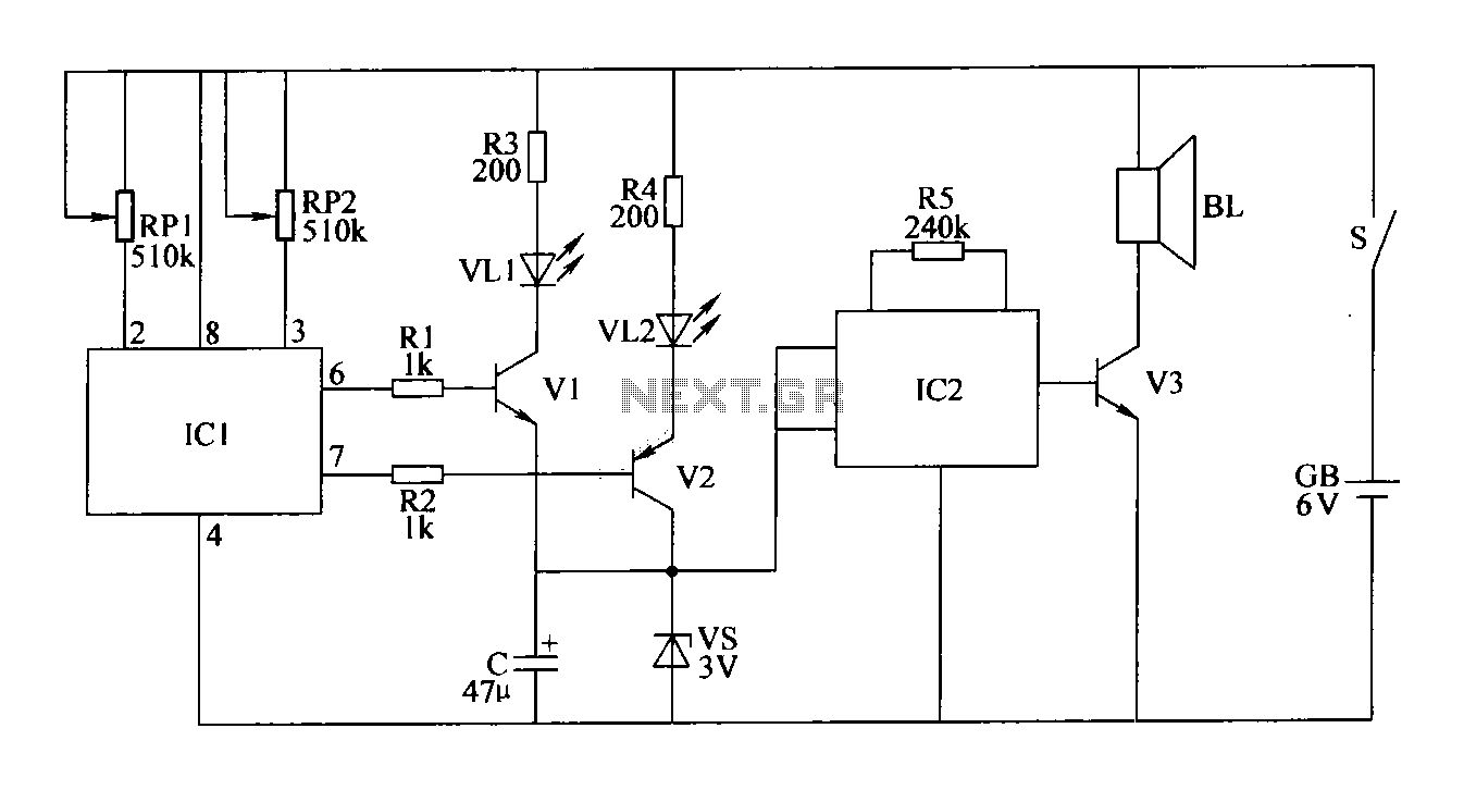
The double-limit temperature alarm circuit consists of a temperature detection control circuit, a temperature indicating circuit, and an alarm sound circuit. The components selected include resistors R1 to R5, which should be 1/4W metal film or carbon film resistors....

This is the circuit diagram of a touch-activated alarm system that remains operational during power outages. The alarm system is triggered when someone touches the designated touch plate. A notable feature of this circuit is the automatic battery activator,...

The design of a wireless data communication circuit is primarily intended for motor vehicles and fixed base station systems to facilitate close-range wireless data exchange. The circuit is based on the core chip nRF401 and its associated components. The...
The schematic presented is a circuit designed for monitoring plant watering, also known as a dry soil detector. Indoor plants, whether in homes or offices, require more attention compared to outdoor plants. Due to busy schedules, it is common...

The Basic Alarm Circuit features an automatic Exit/Entry Zone, which includes an Instant Alarm Zone capable of accepting both normally-closed and normally-open triggering devices, alongside an "Always On" 24-hour Personal Attack/Tamper Zone. Expansion Modules can be used to add...
The circuit operates by monitoring the water level in a tank. When the water level falls below a specified point (F), the RS flip-flop (F2) is activated, producing a high Q output that energizes a relay to start the...