
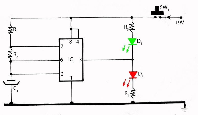
555 timer touch activated alarm circuit
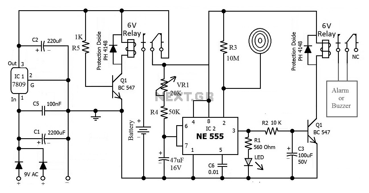
The touch-activated alarm system consists of several key components that work together to ensure reliable operation. The primary component is the touch plate, which serves as the input interface. When a user touches the plate, it sends a signal to a microcontroller or a simple transistor circuit that acts as the trigger mechanism. This signal activates the alarm, which may include a buzzer or siren, alerting users to unauthorized access.
To enhance the system's functionality, an automatic battery activator is integrated into the design. This component is typically a relay that switches the power source from the main supply to a backup battery when a power outage is detected. The relay is controlled by a voltage sensing circuit that monitors the main power supply. If the voltage drops below a certain threshold, indicating a power failure, the relay activates, connecting the backup battery to the alarm system. This ensures that the alarm remains functional even during load shedding.
The circuit may also include additional features such as LED indicators to show the status of the system, a reset button to deactivate the alarm after it has been triggered, and a timer to prevent false alarms from accidental touches. The components are arranged on a printed circuit board (PCB) for compactness and ease of assembly.
Overall, this touch-activated alarm system is versatile and can be adapted to various security needs, providing a reliable solution for protecting homes, vehicles, and personal belongings.This is the circuit diagram of touch activated alarm system which still activated on load shedding. Alarm system will be activated when someone touch the touch plate which is called trigger. In this circuit the most updated part is automatic battery activator which is made by a relay. So don`t upset on load shedding you alarm system is activate d. This circuit could be used at your home door, locker, vehicle or metal gate etc. 🔗 External reference
Related Circuits
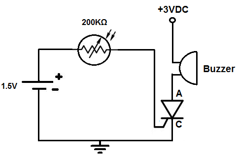
This circuit activates an alarm when it detects a specific level of light. When the light exposure increases beyond a predetermined threshold, a loud buzzer sounds, providing an alert. The alarm remains inactive in low-light conditions but triggers in...
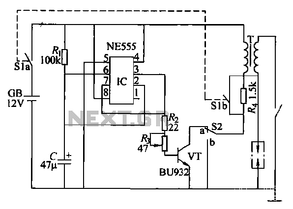
This paragraph describes an easy car alarm circuit that utilizes fewer components and is simple to produce. The circuit consists of an automobile anti-theft alarm system based on the NE555 timer, a power switch (VT), and a switch (S2),...
An FM transmitter circuit that utilizes a low power configuration, employing an operational amplifier as an audio preamplifier and a single transistor to function as the RF amplifier. This FM transmitter circuit is designed for low power applications, making...

This subwoofer filter set is suitable for use with a high-quality car audio system. The circuit is designed to operate with a 12-volt DC power supply. The subwoofer filter set serves as an essential component in enhancing the audio experience...
This analog switch circuit is designed to switch an analog line on or off. It consists of two analog switches in integrated circuit (IC) form that are controlled by two pushbuttons. The described analog switch circuit utilizes two integrated analog...
The integrated circuit (IC) tester featured on this website is specifically designed for the LM555 timer IC. This circuit is utilized for testing the functionality of the timer IC, and it includes a circuit diagram along with techniques for...