
ds18b20 using 1 wire
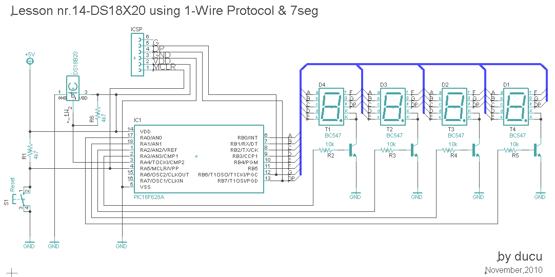
The circuit utilizes a DS18B20 digital temperature sensor, which communicates with the microcontroller (PIC16F628A) via a single wire protocol. This communication method allows for a simplified wiring setup, reducing the number of connections needed. The DS18B20 sensor is capable of providing precise temperature readings, which are subsequently processed by the microcontroller.
The microcontroller is programmed to read the temperature data from the sensor and display it on a multiplexed 7-segment display. The display consists of four digits, each controlled by specific pins on PORTA. The segments of the display are driven by PORTB, where each segment corresponds to a specific bit in the output register. The multiplexing technique is employed to cycle through each digit rapidly, creating the illusion that all digits are lit simultaneously.
The software logic includes functions for masking the output values to correspond to the segments of the display, as well as routines for reading temperature data from the DS18B20. The temperature is read using a series of commands sent via the one-wire interface, including a reset command, a command to skip the ROM, and a command to convert the temperature reading. The resulting temperature value is processed to determine if it is negative and to round the value appropriately before displaying it.
In summary, this digital temperature meter project effectively demonstrates the integration of a temperature sensor with a microcontroller to produce a user-friendly display of temperature readings. The use of multiplexing for the display and one-wire communication for the sensor exemplifies efficient design practices in electronic circuit development.In this Lesson, we will make a digital temperature meter using DS18B20. The connection between temperature sensor and microcontroller will be done through a single wire. This is advantage of the temperature sensor model. The temperature value will be displayed on 4 digits-with 7 segment, in multiplexed mod of course. /* ` <7465> * ` Lesson nr. 14: ` Digital thermometer with DS18B20 and 7- Segments. ` Done by: ` Aureliu Raducu Macovei, 2010. ` ` In this experiment we will work with one-wire communication. ` The thermal sensor used is "DS18B20" and measured value is displayed ` on the 7-segment digits. PORTB will be used for character ` (RB0=a, RB1=b. RB6=g, RB7=dp)and for digits RA0=digit1. RA3=digit4. ` Data wire from DS18B20 is conected to RA4. ` Test configuration: ` MCU: PIC16F628A ` Test. Board: WB-106 Breadboard 2420 dots ` SW: MikroC PRO for PIC 2010 (version v4. 15) ` Configuration Word ` Oscillator: INTOSC:I/O on RA. 6, I/O on RA. 7 ` Watchdog Timer: OFF ` Power up Timer: Disabled ` Master Clear Enable: Enabled ` Browun Out Detect: Enabled ` Low Voltage Program: Disabled ` Data EE Read Protect: Disabled ` Code Protect: OFF ` <7465> * */ unsigned short i, DD0=0x40, DD1=0x40, DD2=0x40, DD3 =0x61, N_Flag; unsigned temp_value=0; // Variable to store temperature register value unsigned short mask(unsigned short num) // Mask for 7 segment common cathode; { switch (num) { case 0 : return 0x3F; // 0; case 1 : return 0x06; // 1; case 2 : return 0x5B; // 2; case 3 : return 0x4F; // 3; case 4 : return 0x66; // 4; case 5 : return 0x6D; // 5; case 6 : return 0x7D; // 6; case 7 : return 0x07; // 7; case 8 : return 0x7F; // 8; case 9 : return 0x6F; // 9; case 10 : return 0x40; // Symbol `-` case 11 : return 0x61; // Symbol C case 12 : return 0x00; // Blank } //case end } void display_temp(short DD0, short DD1, short DD2, short DD3) { for (i = 0; i<=4; i+) { PORTB = DD3; RA0_bit = 1; // Select C Digit; RA1_bit = 0; RA2_bit = 0; RA3_bit = 0; delay_ms(2); PORTB = DD0; RA0_bit = 0; RA1_bit = 1; // Select Ones Digit; RA2_bit = 0; RA3_bit = 0; delay_ms(2); PORTB = DD1; RA0_bit = 0; RA1_bit = 0; RA2_bit = 1; // Select Tens Digit; RA3_bit = 0; delay_ms(2); PORTB = DD2; RA0_bit = 0; RA1_bit = 0; RA2_bit = 0 ; RA3_bit = 1; // Select +/- Digit; delay_ms(2); }return; } void DS18B20() //Perform temperature reading { Display_temp(DD0, DD1, DD2, DD3); Ow_Reset(&PORTA, 4); // Onewire reset signal Ow_Write(&PORTA, 4, 0xCC); // Issue command SKIP_ROM Ow_Write(&PORTA, 4, 0x44); // Issue command CONVERT_T Display_temp(DD0, DD1, DD2, DD3); Ow_Reset(&PORTA, 4); Ow_Write(&PORTA, 4, 0xCC); // Issue command SKIP_ROM Ow_Write(&PORTA, 4, 0xBE); // Issue command READ_SCRATCHPAD Display_temp(DD0, DD1, DD2, DD3); // Next Read Temperature temp_value = Ow_Read(&PORTA, 4); // Read Byte 0 from Scratchpad temp_value = (Ow_Read(&PORTA, 4) << 8) + temp_value; // Then read Byte 1 from // Scratchpad and shift // 8 bit left and add the Byte 0 if (temp_value & 0x8000) { temp_value = ~temp_value + 1; N_Flag = 1; // Temp is -ive } if (temp_value & 0x0001) temp_value += 1; // 0. 5 round to 1 temp_value = temp_value >> 4 ; //<<< // 1 for DS1820 and // 4 for DS18B20; } void main() { CMCON |= 7; // Disable Comparators TRISB = 0; // Set PORTB direction to be output PORTB = 0; // Turn OFF LEDs on PORTB PORTA = 0; TRISA0_bit = 0; // RA. 0 to RA3 Output TRISA1_bit = 0; TRISA2_bit = 0; TRISA3_bit = 0; do { //- main loop N_Flag = 0; // Reset Temp Flag DS18B20(); DD0 = temp_value%10; // Extract Ones Digit DD0 = mask(DD0); DD1 = (temp_value/10)%10; // Extract Tens Digit DD1 = mask(DD1); DD2 = temp_value/100; // Extract Hundred digit if (N_Flag = 1) DD2=0x0A; // DD2 10 else if (DD2 = 0) DD2 = 0x0D; // DD2 13 DD2 = mask(DD2); display_temp(DD0, DD1, DD2, DD3); // Infinite loop; } while (1); }
🔗 External reference
Related Circuits
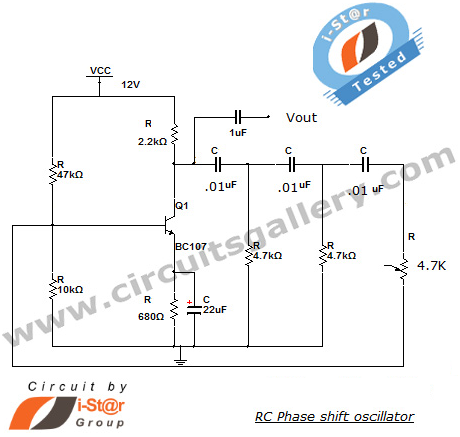
This section introduces a transistor oscillator circuit known as the RC Phase Shift Oscillator. An oscillator is an electronic circuit that functions as a sine wave generator, requiring only a DC power supply. It is commonly used in variable...
This project focuses on the development of a low-cost cosmic ray detector utilizing common fluorescent tubes. It is based on an experiment conducted in 2000 by Dr. Schmeling at CERN, which demonstrated a straightforward method for detecting and visualizing...
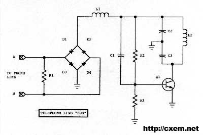
Wireless Telephone Bug. This project enables monitoring of a phone line as soon as the phone is off-hook. A regular FM broadcast band radio can be utilized for this purpose. The Wireless Telephone Bug is a circuit designed to allow...

The circuit utilizes a 555 timer IC to create a lighting group delay effect, as illustrated in Figure 2-46. It consists of the 555 IC along with a resistor and capacitor configuration that establishes the delay. The circuit remains...
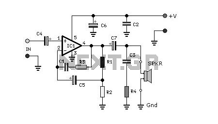
The circuit is designed to deliver approximately 10% distortion on a 4 Ohm to 8 Ohm loudspeaker. The LM4756 amplifier can output 7W of power. Utilizing four pairs of 2SC5200 and 2SA1943 transistors, this configuration can generate around 500W....
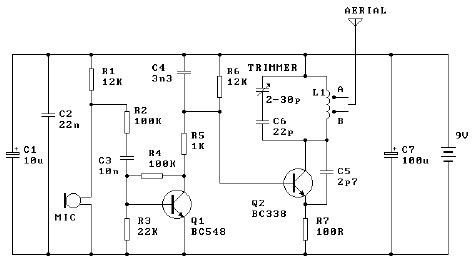
The tuned coil L1 has two output tap points for the antenna connection, labeled "A" and "B." Both outputs are low-level, allowing the user to select between a stable low range or a more unstable but higher range. Tap...
Warning: include(partials/cookie-banner.php): Failed to open stream: Permission denied in /var/www/html/nextgr/view-circuit.php on line 713
Warning: include(): Failed opening 'partials/cookie-banner.php' for inclusion (include_path='.:/usr/share/php') in /var/www/html/nextgr/view-circuit.php on line 713