
Cosmic Ray Detector using Fluorescent Tubes
The cosmic ray detector circuit operates by utilizing fluorescent tubes as the primary sensing element. The setup consists of three metal plates arranged to create an electric field across the tubes. The outer plates serve as the cathode while the center plate acts as the anode, creating a potential difference when connected to a high voltage power supply. The high voltage, typically around 650V DC, is critical for the ionization process.
When a cosmic ray, specifically a muon, passes through the fluorescent tube, it ionizes the gas inside, causing a decrease in resistance between the plates. This phenomenon allows for the detection of the muon as it triggers a measurable change in current flow through the circuit. The dual-row configuration of fluorescent tubes enhances detection capabilities by allowing for the identification of coincidences, which can help distinguish between cosmic events and terrestrial noise.
The use of an RC network to control the biasing of the fluorescent tubes is an innovative approach, as it was initially intended to prevent sustained ionization and produce a pulse. However, the unexpected voltage spikes observed indicate that the system may inherently generate detectable signals without the need for biasing. This aspect of the design warrants further investigation to determine the precise mechanisms at play.
To improve the reliability of the measurements, the circuit should incorporate robust filtering and noise-reduction techniques. This may involve utilizing high-quality capacitors for smoothing out voltage fluctuations and ensuring stable operation of the high voltage supply. Additionally, implementing shielding and grounding techniques can minimize external interference, enhancing the accuracy of cosmic ray detection.
In summary, this project presents a promising approach to cosmic ray detection using readily available materials. The design leverages the principles of ionization and electric fields to create a functional detector, while also highlighting the challenges associated with distinguishing cosmic signals from noise. Continued refinement of the circuit and thorough testing will be essential to validate the effectiveness of this low-cost cosmic ray detection system.This project was deliberately aimed at developing a very low cost cosmic ray detector using common Fluorescent Tubes. It was based on variation of an experiment performed in 2000 by the CERN (European Organization for Nuclear Research) laboratories by Dr.
Schmeling which found a simple method for detecting and visualizing cosmic rays using everyda y fluorescent tubes inside a wire mesh of feed with a high voltage. However one of the very best websites I have found on working Fluorescent Tube cosmic ray detectors is if you are interested in this type of design you could do no better. I have now begun building a number of other types of detectors due to a number of issues I identified in my design using Fluorescent Tubes below is what I had done so far.
My first detector prototype was not that dissimilar to the CERN example, except the fluorescent tubes are placed between three metal plates. The outer plates are connected together by bolts and connected to the Negative rail of the supply and the centre plate is insulated by the fluorescent tubes and connected to the Positive rail of the supply.
So far I have found the best result with small 6W fluorescent tubes is around 650V DC Like the CERN example, when a muon flys through the fluorescent tube, the gas inside ionizes due to the high voltage field across the plates. As a result of the ionization the resistance across the plates will fall slightly and so it should be possible to measure this as a change in current flow in the high voltage source.
The reason for two rows of fluorescent tubes is to sense the crude presents of coincidence occurring in the top and bottom rows of fluorescent tubes due to a muon flying through both. I`m speculating that the resistance in the detector should be half compared with only one row detecting something, due to terrestrial noise.
If the output is feed into a data logger and also speculate that over time the difference between cosmic and terrestrial detections could be filtered. I couldn`t help noticing the similarity with flash tubes and other types of gas filled trigger electronics like a Thyratron thermionic valve.
Basically these tubes are biased at a voltage below ionization and when a high voltage trigger is applied briefly in the gas path between the Cathode and Anode, the gas to within the tube ionizes, the resistance to falls rapidly between the Cathode and Anode and like SCR current flows until power is removed. Consequently I tried biasing the individual fluorescent tubes using their standard electrodes with a DC voltage somewhere below their point of ionization ~70V through a high impedance RC network.
The RC network preventing sustained ionization, so producing just a pulse. However, to my surprise I got quite the opposite, as I measured a voltage spike across the electrodes rather than a dip and so it would seem biasing may not be required as a strong positive spike can be clearly observed on a CRO without any biasing. Nevertheless, even though "something" is causing clear observable pulses on a CRO in all variations tested above, it is difficult to confirm they are actually due to Cosmic Rays or Terrestrial Radiation over something like coronal discharges within the tube itself.
All attempts to find RFI sources have drawn a blank as pulses disappeared when the high voltage supply was switched off, other Electrical Interference has also been ruled out shielding inside a metal box. I also ruled out the supply itself without the detector and could not find any other interference sources.
I should also note that early in my building and testing of these ideas, I found that most HV supplies I built had quite allot of noise or ripple present, specially the type often recommended for Geiger Counters, so I spent quite a bit of time trying to eliminate this, with improved voltage regulation and a good bank of capacitors. Tests with an xray source have confirmed the system dos 🔗 External reference
Related Circuits
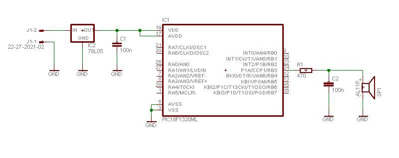
This project enables a PIC microcontroller to play audio PCM sounds using PWM modulation. Pulse-code modulation (PCM) is a digital representation of audio signals. The project utilizes a PIC microcontroller, which is programmed to generate audio signals through pulse-width modulation...
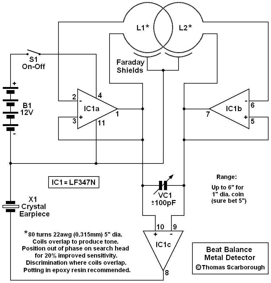
Various embodiments of the BB metal detector have been published, and it has been widely described in the press as a new genre. Instead of using a search and a reference oscillator as with BFO, or Tx and Rx...
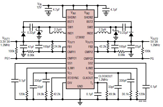
The LT3692 dual current mode PWM step-down DC-DC converter circuit, featuring two internal 3.5A switches, can be designed into a simple power supply circuit suitable for various electronic applications, such as distributed supply regulation or automotive circuits. The LT3692...
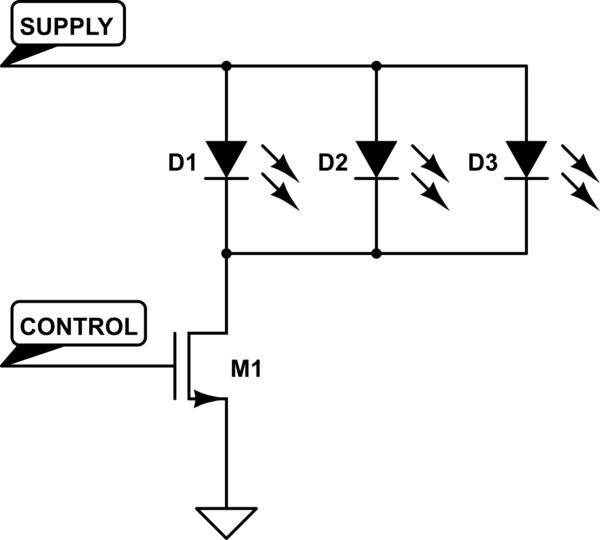
A Common Cathode LED strip is being utilized instead of a Common Anode variant, leading to the development of a modified circuit. The experience with FETs was limited, resulting in challenges as a minimum voltage equal to Vcc is...
A simple rotating display. Just spin and enjoy. While the "Air display" is rotating, it writes the message on the air. Because of the "persistence of vision", you will be able to read the message. The operation is super...
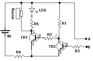
This document presents a water sensor circuit designed to monitor soil moisture levels for plants. This circuit is straightforward and is constructed using five resistors, two transistors, an LED, a buzzer, and a battery. The operation of the circuit...