
dspic servo

The circuit schematic for this project consists of several key components and connections. The dsPIC 30F4012 microcontroller serves as the central processing unit, interfacing with the power operational amplifier that drives the DC motors. The microcontroller's output pins are connected to the power amplifier's input to control the motor's speed and direction based on the quadrature drive signals received from the parallel port. The power amplifier is configured in constant current mode to ensure stable operation under varying load conditions.
The microcontroller is connected to a serial port for tuning and configuration purposes, allowing for real-time adjustments to the PID control parameters. An encoder is integrated into the motor system, providing feedback on the motor's actual position, which is crucial for the servo loop's operation. The encoder output connects to the microcontroller's input pins, enabling the loop to compare the commanded position with the actual position continually.
For power supply, a dedicated voltage regulator circuit is included to ensure that the microcontroller and power amplifier receive the appropriate voltage levels, protecting the components from overvoltage conditions. The PCB layout should account for the placement of surface mount and through-hole components, ensuring minimal interference and optimal signal integrity.
The overall design emphasizes modularity and ease of assembly, with clear labeling of connections and components on the PCB. Given the use of common components and straightforward assembly techniques, this project is accessible for those looking to implement a low-cost servo control system for CNC applications.This project was developed as an inexpensive way to drive small dc brushed motors as positioning servos for use on a desktop sized CNC machine. The board is interfaced to the PC through 2 pins of a parallel port. The drive signal on these pins is known as quadrature drive. The power stage consists of a power op amp driven in constant current mode. The internal PIC processor ( a 30f4012 from Microchip ) is programmed in C through the C30 compiler and the Microchip IDE. The servo loop parameters are programmed through a serial port connection and are saved in the dspic eeprom.
Once set for a particular drive, they should not need to be changed. The serial programming interface is used to tune the PID and other servo loop parameters to optimize the performance in a particular application. The serial port runs at a fixed baud rate of 9600N81. Any terminal program such as minicom, gtkterm, or hyperterminal may be used to talk to the dspic-servo.
On powerup you will see the following: Powerup. i/o. uart. timer. pwm. pid. encoder. capture. done dspic-servo by L. Glaister (c)25-Sept-2006 by VE7IT using setup from eeprom. for help Current Settings: servo enabled = 1 (p) = 0. 020000 (i) = 0. 000000 (d) = 0. 000050 FF(0) = 0. 000000 FF(1) = 0. 000000 dead(b)and = 1. 000000 (m)ax output = 2. 500000 (f)ault error = 1024. 000000 (x)pc cmd multiplier = 3 (t)icks per servo cycle= 10 The current values will be redisplayed with the new value set. The p, i, d, ff0 and ff1 values are standard loop gain parameters. You can reference the source code for a better explanation. The deadband parameter is the number of encoder counts the servo can be out of position without the servo loop taking any corrective action.
The max output is the maximum current output allowed in amps and should be set for the particular motor you are using. This number can be up to 7 amps. The fault error parameter is used to set the number of counts the servo can be out of position before the drive gives up and indicates a drive fault.
This is used to detect crashes and jammed axis or input command conditions beyound the capabilities of the motor. The pc command multiplier is useful for cases where you have a high resolution encoder on the motor and a PC that is limited in the number of pulses/second it can output.
For most operation this number will be set to 1, but if you have trouble reaching the top speed you need from the drive, it may be helpful to set this number to a higher value. The internal servo loop works by keeping 2 counters. The first is the commanded position from the PC, the second is the actual position from the encoder. The servo loop of the drive attempts to keep these 2 numbers as close as possible to each other. The ticks per servo cycle gives a way to set how often the pid calculation cycle is run. The number is the count of how many times the internal 100us interrupt fires between requesting the servo calculations.
This can be set as low as 2 (200us or 5khz servo rate) to as high as 100 (0. 01sec or 100hz servo rate). After this number is changed, you must power down the servo card and restart it to make the rate change. With the motors I am using, I found no advantage to slower or faster rates than the standard value of 10 ( 1khz rate ).
You will need a programmer for the dspic processor, the Microchip IDE evironment and the C30 compiler (demo version OK) from Microchip. Although the design uses a combination of surface mount and through hole components, the larger 1206 size surface mount components are easy to work with without special equipment.
The single sided circuit board can be etched or if you have a milling machine, these boards can be milled using the pcb-gcode. ulp program available for the eagle pcb software. 🔗 External reference
Related Circuits

A servo consists of a small motor and gear mechanism that rotates a shaft to a precise location and maintains that position. The image displays a typical servo with its cover removed. The shaft's position is controlled by a...
The figure illustrates a schematic for an oscillator amplitude-control servo system. The circuit establishes a closed-loop system that provides a fixed and adjustable peak-to-peak amplitude AC signal centered around 0 V. A 1 kHz sine wave, designated as AC_INPUT,...
This study utilizes a motor potentiometer available from All Electronics at a low cost of $4.00. The catalog number is MPOT-10K, manufactured by Alps, with the motor marked MD157320 and the body labeled 725t 10BX2. The potentiometer is a...
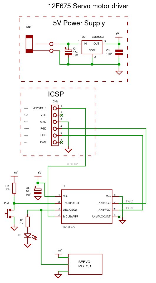
How to generate the signal for controlling a standard (RC) servo motor using a PIC microcontroller. To control a standard RC servo motor with a PIC microcontroller, it is essential to generate a pulse-width modulation (PWM) signal that dictates the...
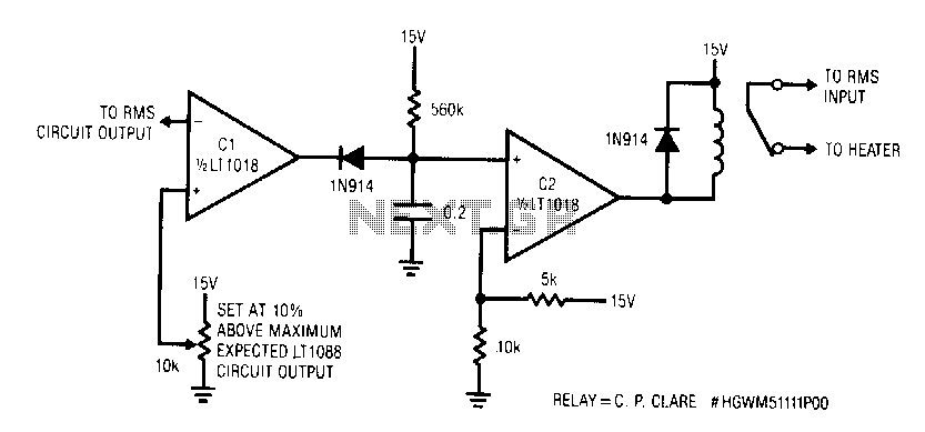
This circuit responds quickly enough to prevent damage from most overloads. Capacitor C1's input is connected to the output of the LT1088 servo circuit. If the LT1088 circuit's output exceeds the threshold at C1's other input, C1 trips, discharging...
This involves controlling servo motors through software programming using the PIC 16C71 microcontroller. The input signals range from 0 to 5V. The circuit for controlling servo motors with a PIC 16C71 microcontroller is designed to provide precise control over the...