
Servo Circuit Controls Sine-Wave Amplitude
The oscillator amplitude-control servo system operates on the principle of feedback control to maintain a specified output amplitude. It consists of several key components, including an AD633 multiplier, a peak detector, an error integrator, and an adjustable reference voltage source. The AD633 multiplier is a versatile device that multiplies two input signals, in this case, the AC_INPUT and the SERVO signal. The output from the multiplier is a scaled version of the AC_INPUT, facilitating the generation of the desired output amplitude.
The peak detector is crucial for identifying the maximum value of the output waveform. It converts the AC signal into a DC voltage that corresponds to the peak amplitude of the sine wave. This DC voltage is then compared to a user-defined reference voltage, which serves as the target amplitude for the output signal. The difference between the detected peak and the reference voltage is processed by the error integrator, which accumulates this error over time to generate a corrective signal—the SERVO signal.
This SERVO signal is fed back into the multiplier, adjusting its output to ensure that the amplitude of the AC signal matches the reference voltage. This feedback loop allows for precise control of the output amplitude, making the system adaptable to various input conditions. The flexibility of the circuit is highlighted by its ability to operate with different input frequencies and amplitudes, as demonstrated in testing with a 1 kHz sine wave input at 4.5 V, which yielded a stable output of 1 V.
Overall, the oscillator amplitude-control servo system is an effective solution for applications requiring consistent and adjustable AC signal amplitudes, leveraging the principles of feedback control and signal processing to achieve its objectives.The figure shows a schematic for an oscillator amplitude-control servo system. The circuit creates a closed-loop system that supplies a fixed and adjustable peak-to-peak amplitude ac signal centered around 0 V. A 1-kHz sine wave, labeled AC_INPUT, is ac-coupled to an AD633 multiplier chip. Then the AC_INPUT is multiplied by the SERVO signal. The m
ultiplier`s output is a scaled version of the AC_INPUT. This 1-V sine output signal is fed into a peak detector, and the peak of the signal is compared to a user-supplied reference voltage. The error integrator integrates the difference between the peak and the reference. This generates the servo signal that feeds the multiplier. The servo signal will force the peak amplitude of the AD633 output to match that of the user-supplied dc reference at the error integrator.
The ac-coupling of the input signal and the frequency of the input signal are not fixed requirements. The circuit was successfully tested using a 1-kHz sine wave for the input with an amplitude of 4. 5 V, and it produced a 1-V amplitude sine-wave output using a 1-V reference for the set point.
Related Circuits
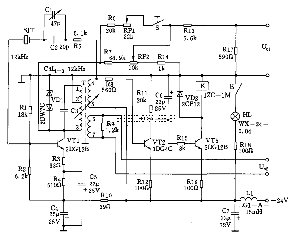
The circuit features a 12kHz intermediate frequency (IF) oscillator utilizing a quartz crystal for precision frequency generation. It includes components for output level adjustment, a level-up circuit, and an alarm circuit. The design employs a unique single-tuned variable feedback...
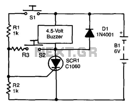
A self-interrupting device connected to a voltage source operates as a switch that continuously opens and closes; thus, the circuit does not latch in the conventional manner, allowing the alarm to function only while switch SI is closed. Due...
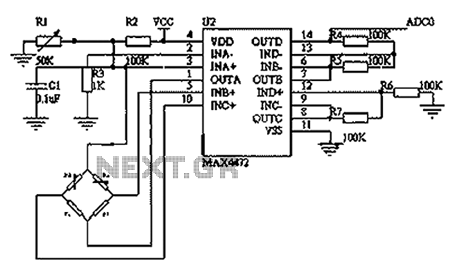
This circuit utilizes a BP01-type pressure sensor and the MAX4472 operational amplifier. The BP01 pressure sensor is specifically designed for blood pressure detection and is primarily used in portable electronic sphygmomanometers. It features a precision thick film ceramic chip...
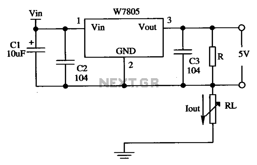
The circuit is composed of a W7805 positive current source application integration circuit that includes a voltage regulator. The W7805 regulator operates in suspension. A resistor is placed between its output terminal and the common terminal, forming a constant...
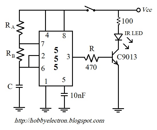
The remote control circuit comprises two main components: a transmitter and a receiver. The transmitter circuit is controlled by an NE555 integrated circuit (IC), while the receiver operates based on the frequency of the signal emitted by the transmitter....
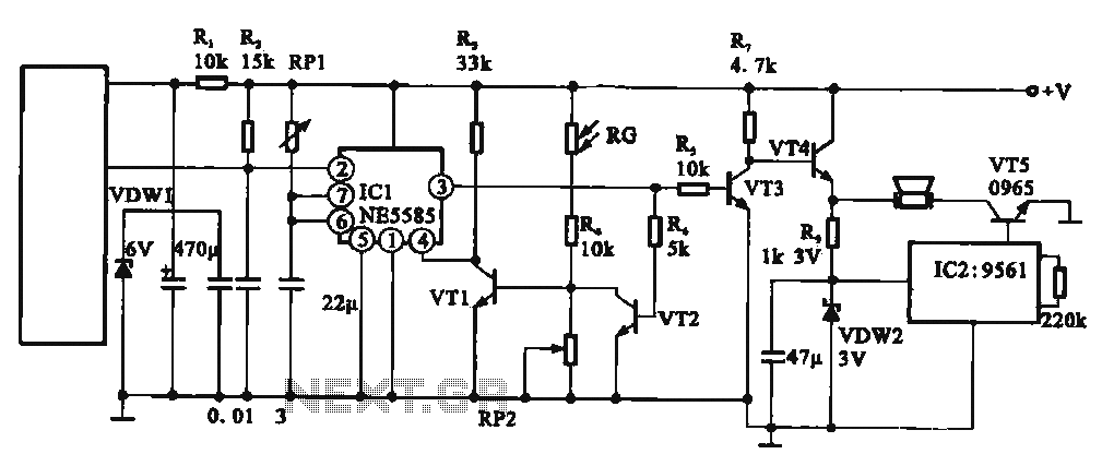
This circuit illustrates an automatic unattended burglar alarm system designed primarily for residential use, warehouses, and similar applications. The circuit features a pyroelectric infrared sensor integrated with a light control mechanism. It comprises components such as resistors (RG, RP2,...