
servo motor
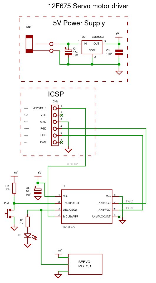
To control a standard RC servo motor with a PIC microcontroller, it is essential to generate a pulse-width modulation (PWM) signal that dictates the position of the servo. The PWM signal is characterized by its duty cycle, which determines the angle of the servo arm. Typically, a standard RC servo motor expects a PWM signal with a frequency of approximately 50 Hz, where the pulse width ranges from 1 ms to 2 ms. A 1 ms pulse corresponds to a 0-degree position, while a 2 ms pulse corresponds to a 180-degree position.
The process begins with configuring the PIC microcontroller's timer to generate the PWM signal. For instance, Timer 1 can be set up in the PIC microcontroller to create an interrupt that occurs at a frequency of 50 Hz. The interrupt service routine (ISR) will then toggle a digital output pin connected to the servo control line. The width of the pulse can be adjusted by modifying the timer's compare register, allowing for precise control over the servo's position.
The following steps outline the implementation:
1. **Configuration of Timer**: Set up Timer 1 in the PIC microcontroller to generate interrupts at a frequency of 50 Hz. This involves setting the appropriate prescaler and period values based on the microcontroller's clock frequency.
2. **PWM Signal Generation**: In the ISR, toggle the output pin connected to the servo. The pulse width can be controlled by using a variable that defines the duration of the high state of the output pin. This variable should be set to correspond with the desired angle of the servo.
3. **Mapping Angles to Pulse Widths**: Create a function that maps the desired angle (0 to 180 degrees) to the corresponding pulse width (1 ms to 2 ms). This can be achieved through a linear interpolation based on the angle input.
4. **Output to Servo**: Ensure that the output pin is connected to the control line of the servo motor. The servo will respond to the PWM signal by adjusting its position according to the pulse width received.
5. **Testing and Calibration**: Once the circuit is assembled, it is crucial to test the output signal with an oscilloscope to confirm that the pulse widths are accurate and correspond to the desired angles. Calibration may be necessary to account for any discrepancies between the expected and actual servo positions.
By following these steps and ensuring proper configuration of the PIC microcontroller, a reliable control signal for a standard RC servo motor can be generated, enabling precise movement and positioning in various applications.How to generate the signal for contolling a standard (RC) servo motor using a PIC microcontroller.. 🔗 External reference
Related Circuits
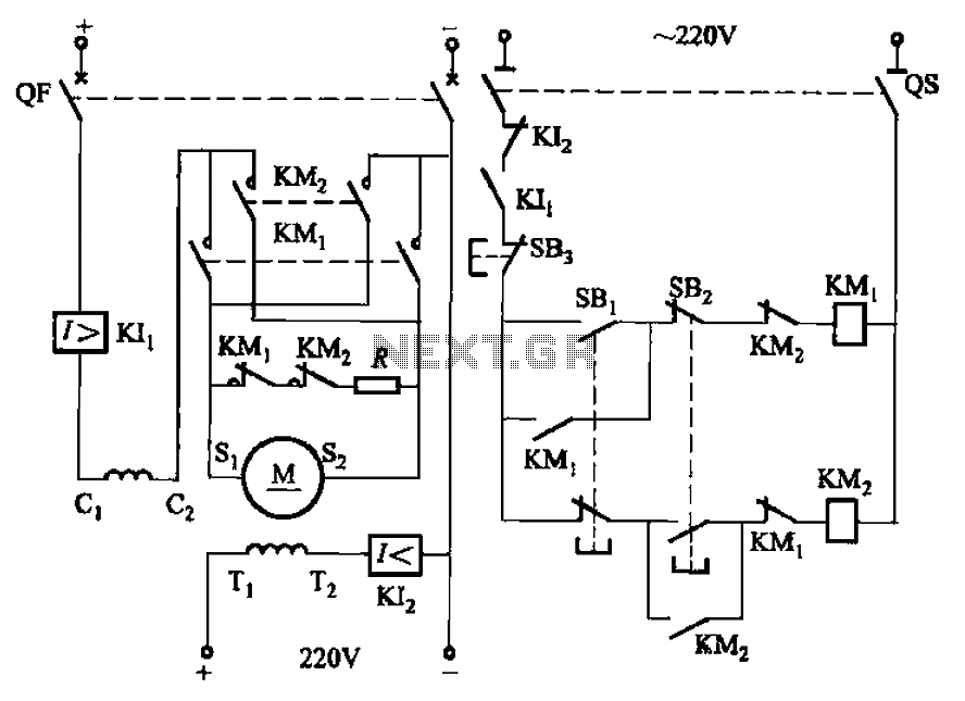
The circuit depicted in Figure 3-194 features a re-excitation type DC motor with six terminals: S1 and S2 for the armature windings; C1 and C2 for the series excitation (field) windings; and T1 and T2 for the shunt (field)...
The second half controls the steering. The mechanical design is a 3 wheeled caddy with the single wheel actually a closely spaced pair of wheels which are driven by the main drive motor to provide motive power (this is...
Figure 2-32 (a) illustrates the time control diagram for a motor operated by switch S1. When S1 is set to position 1, the power driver circuit supplies current to the motor, enabling it to run. When S1 is switched...
Closed loop motor control is utilized for maintaining constant speed in motor operations. This means that the motor's speed is regulated to remain steady. Closed loop motor control systems, commonly referred to as servo control systems, are essential in applications...
This 3A charger was originally designed to work with small batteries like those used in motorcycles. In principle it can be used to charge car batteries also but will take a lot longer. The charger below charges a battery...
Two inputs, A and B, control the bridge. With both high (or open circuit) both ends of the motor are connected to 0v. Connect A low and Tr2 turns on causing the motor to go forward. Connect B low...