
DTMF Decoder
The decoder stores the last 255 received digits in EEPROM. The contents of EEPROM can be viewed on the LCD screen via two scroll buttons. Total power consumption is 17mA. The DTMF decoder has three inputs. A RJ11 jack for connecting to the phone line. A 1/8" audio jack for connecting to a scanner, tape recorder or other audio output device. A microphone with a 6-12" range. A PCB layout is provided if one wishes to construct their own PCB. Simply print the file at 1:1 onto an overhead transparency. (Get the correct sheet for your type of printer) I used a kit by MG Chemicals ( E-Sonic Search for 416-K) to produce my PCB. The provided PCB layout`s smallest traces are 15 thou wide. Drill the holes for the headers at 40 thou. Drill the holes for the 20K POT, the buttons, and the audio jack at 35 thou. Drill the rest of the holes at 30 thou. Drill bits can be found a most hobby stores. Review the schematic and parts placement diagram before beginning assembly for proper orientation of diodes, ICs and capacitors.
Begin by installing the seven jumper wires. Next solder in all the resistors and capacitors. Then solder in the buttons, the phone and audio jack, the two headers, the 20K POT and the crystal. Solder in the 20 pin socket, ICs, diodes and Mic. Be sure that the Mic`s ground (tab that has traces connected to Mic`s case) goes to the decoder`s ground. Finally install the two, seven pin headers into the LCD (short side towards LCD). Solder the longer side of the headers into the DTMF decoder PCB. Attach the LCD and decoder together with hot glue or other means. At this point, test the decoder for +5V between pins 10 and 20 on the 20 pin socket. Programming the Atmel AVR AT90S2313 is the final step. A programmer can be bought from Digikey (Search for STK500). Here is a link to a simple AVR programmer. Simply Write dtmf. hex to the 2313 and then install the micro into the DTMF decoder. Power the decoder up, adjust the contrast, and the message "DTMF Decoder. " should appear on the screen. To use the DTMF decoder, simply connect it to a 9V battery and the phone line. The DTMF decoder will accept ISOLATED DC voltages from 7 to 20 V. Upon power up the Message "DTMF decoder by appears on the LCD screen. The message will remain there until a DTMF digit is received or a scroll button is pressed. If a DTMF digit is received while scrolling through EEPROM, the LCD screen is restored and the digit is appended to the end of the line.
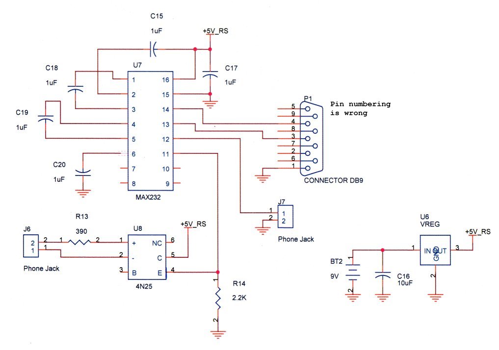
The LCD will auto scroll at the end of each line. Their are two scroll buttons, UP and DOWN. They will shift the last 255 digits through the LCD screen 16 at a time. UP will move towards the oldest received digit while DOWN will move towards the most recently received digit. A jumper is used to select between the phone line / audio jack input and the microphone. Remember to set the 20K pot for LCD CONTRAST adjustment. To connect the DTMF Decoder to the computer a Serial interface board is used. The interface consists of a MAX232 and a 4N25 Opto-isolator. The interface is TX only. This means that the information can only be sent from the DTMF decoder to the computer. Connect a 9V battery to the interface board. A SEPARATE power source must be used from the DTMF decoder because the phone line must be electrically isol
🔗 External reference
Related Circuits
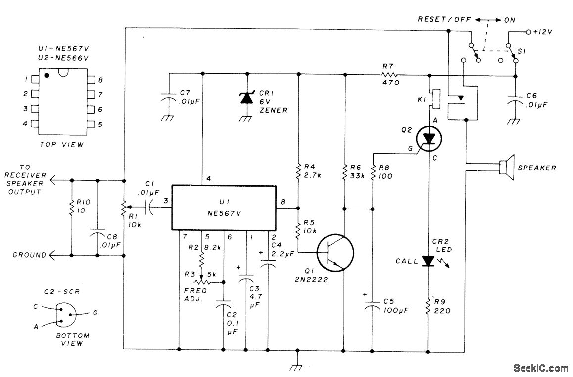
This circuit allows for monitoring a local VHF FM repeater for calls from friends without the need to listen to the background chatter or noise from the repeater. Its operation mimics that of Motorola paging units, where a special...
A block diagram of the stereo TV decoder is presented. It illustrates the overall relationships between the separate sections of the circuit. The decoder section revolves around IC1, a standard 4.5-MHz audio demodulator. The output of IC1 is routed...
This design note presents a simple yet feature-rich 16-watt output, universal AC input adapter power supply for modems, hubs, or similar applications. The circuit utilizes a discontinuous mode (DCM) flyback converter topology designed around ON Semiconductor's NCP1027 monolithic current...
This project displays telephone numbers decoded from tones. A microphone picks up the tones, a preamplifier boosts the signals, an SSI-202 DTMF chip decodes the tones, a Basic Stamp acts as an interface to an LCD display and also...
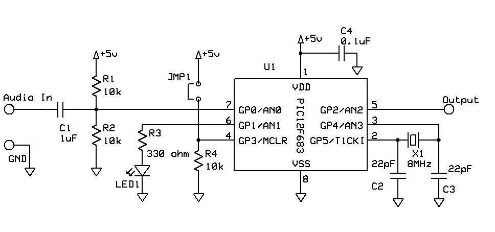
DTMF Touch Tone Decoder Using Microchip PIC Microprocessor. This project contains the details of using a Microchip PIC12F683 8-bit microprocessor to detect Dual-Tone Multi-Frequency (DTMF) signals. The DTMF Touch Tone Decoder circuit utilizes the Microchip PIC12F683 microprocessor, which is an...
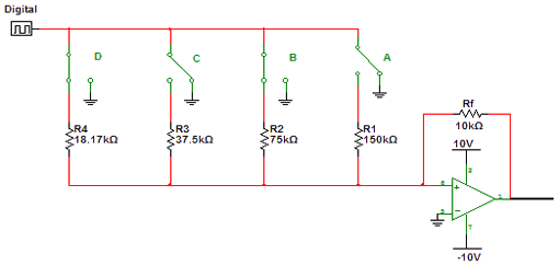
Encoders and decoders are circuits that convert analog signals to digital signals and digital signals to analog signals. The input is in digital form, while the output is a continuous sine wave or analog wave. Encoders and decoders play a...