
Encoder and Decoder
Encoders and decoders play a crucial role in modern electronic systems, facilitating the seamless interaction between digital and analog domains. An encoder is responsible for transforming an analog signal, such as sound or light, into a digital format, which can be processed by digital devices. This process typically involves sampling the analog signal at discrete intervals and quantizing the amplitude to a finite set of values, resulting in a binary representation.
Conversely, a decoder performs the reverse operation, taking a digital signal and converting it back into an analog form. This is essential for applications where digital processing is required, but the output needs to be in a form that can be perceived by humans or other analog systems. The output of a decoder is often a continuous sine wave or other types of analog waveforms that accurately represent the original input signal.
In practical applications, encoders and decoders can be implemented using various technologies, including integrated circuits (ICs) dedicated to signal processing. Common examples include pulse code modulation (PCM) encoders, which convert audio signals into digital data for transmission, and digital-to-analog converters (DACs), which take digital audio data and produce an analog output for speakers.
The design of these circuits requires careful consideration of factors such as sampling rate, bit depth, and noise performance, as these parameters significantly influence the fidelity of the conversion process. Additionally, various modulation techniques, such as amplitude modulation (AM) or frequency modulation (FM), can be employed to optimize the performance of the encoder and decoder in specific applications.
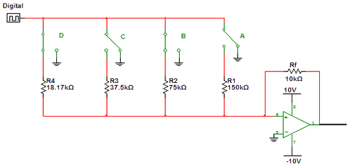
Overall, the integration of encoders and decoders within electronic systems enhances the versatility and functionality of devices, enabling them to operate effectively across both analog and digital environments.Encoder and Decoder are circuits which converts the analog signal to digital and digital signal into analog signal. Its input will be in digital form while the output will be a continuous sine wave or analog wave.. 🔗 External reference
Related Circuits
This is an image Schematic. No Description available. The provided input indicates that there is a schematic image, but no additional descriptive information is available regarding its components, functionality, or application. In the context of electronic schematics, such images...

Q1 is an audio amplifier, and U1 is utilized as a 31.5 kHz subcarrier, which is comparable to the 38 kHz FM multiplex. The pilot frequency is 15.734 kHz. In this circuit, Q1 serves as the audio amplifier, responsible for...
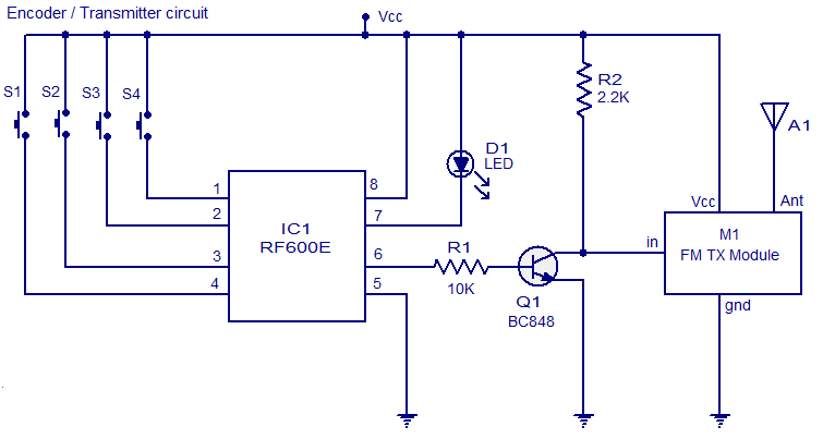
The circuit diagram illustrates an FM remote encoder/decoder utilizing the RF600E and RF600D integrated circuits (ICs). These components are engineered to deliver a high level of security and operate within a voltage range of 2 to 6.6V DC. Applications...

Another application of the frequency-to-voltage converter (FVC) is the tone/frequency decoder. This circuit is designed to identify the frequency band of an oscillating signal. It is utilized in various applications, such as determining the frequency band in signals and...
This circuit detects the dial tone from a telephone line and decodes the keypad pressed on the remote telephone. The dial tone heard when picking up the phone is known as Dual Tone Multi-Frequency (DTMF). The term is derived...
In FM stereo transmission, the left and right audio channels are encoded into sum (left + right) and difference (left - right) signals. This encoding allows mono FM receivers to be compatible with stereo transmissions. The mono receiver reproduces...