
CONTROL TONE DECODER
This circuit is designed for efficient communication in environments where multiple users may be accessing the same VHF FM repeater, thereby minimizing unnecessary noise. The tone encoder, which is unique to each user, ensures that only designated transmissions can trigger the receiver, allowing for a selective monitoring experience.
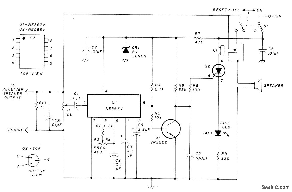
The NE567V PLL is a key component in this circuit, serving as a tone decoder that responds to specific frequencies. Its functionality is critical in distinguishing between the desired tone and other signals, thus preventing false triggering of the loudspeaker. The output from pin 8 of the NE567V is essential for controlling the state of the relay through Q2. When the correct tone is detected, the drop in voltage at pin 8 indicates that the signal is valid, leading to the activation of the relay, which connects the loudspeaker to the audio output.
The use of a relay (K1) in conjunction with the SCR (Q2) allows for a robust switching mechanism that can handle the power requirements of the loudspeaker while ensuring that it remains connected only when a valid call is received. The inclusion of a RESET switch provides a manual means to disengage the loudspeaker, ensuring that the user can quickly silence the output when needed.
The circuit's design also incorporates protection components such as the 1N4735 Zener diode (CR1), which stabilizes voltage levels and protects sensitive components from voltage spikes. The red LED (CR2) serves both as an indicator of the loudspeaker's connection status and as a visual confirmation that the system is operational.
Overall, this circuit provides a streamlined solution for personalized communication over VHF FM frequencies, enhancing the user experience by filtering out unwanted noise while ensuring that important messages are received clearly.Permits monitoring local VHF FM repeater for calls from friends without having to listen to chatter of others or to repeater noise. Operation is similar to that of Motorola paging units in which special tone is transmitted to disable squelch of receiver being called.
Each friend has tone encoder for his transmitter, set at correct frequency for co nnecting loudspeaker so desired call can be heard. Red LED comes on to confirm that loud-speaker is connected. Audio from receiver loud-speaker is fed into pin 3 of NE567V PLL U1. When correct tone frequency is received, pin 8 drops from 4V to near 0V, turning off Q1 and turning on Q2. Q2 closes relay K1, to connect loudspeaker, and holds it on until RESET switch is operated. Q2 is Radio Shack 276-1059 or other small SCR. CR1 is 1N4735, and CR2 is red LED. -K. Wyatt, Private Call System for VHF FM, Ham Radio, Sept. 1977, p 2-64. 🔗 External reference
Related Circuits
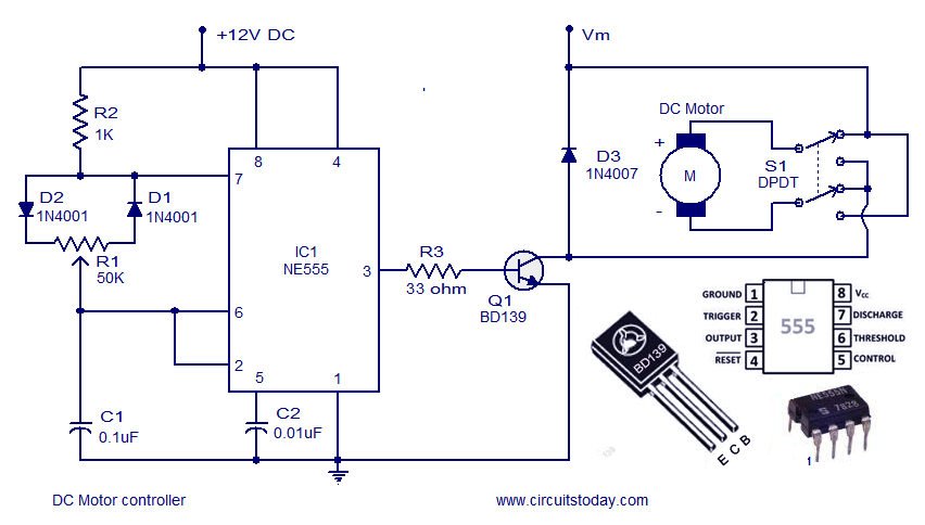
A DC motor controller based on an NE555 timer is presented here. The direction of rotation of the DC motor can also be changed using this DC motor speed control circuit. The described circuit utilizes the NE555 timer IC in...
This Project is made up with AT89C2051 and the RTC DS1307. It has a large Seven segment display. The standard remote control is used to change the Time. More: Procedure to enter the Time 1. Press power button on...
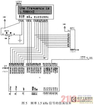
The primary function of the frequency counter is to measure the frequency and cycle of a signal. Its applications span a wide range, extending beyond simple instrument measurements to areas such as education, scientific research, high-precision instrument measurement, and...
The following circuit illustrates the AT90LS2323 Microcontroller Circuit Diagram. Features include a voltage range of 2.7 to 6 volts, and compatibility with all 2323 chips. Components are included. The AT90LS2323 microcontroller circuit is designed to operate within a voltage range...

The intelligent control circuit for the iron is presented. This circuit utilizes the integrated circuit PT8A351X to manage functions such as direction detection, relay control, and LED indication. When the iron is positioned horizontally, it will power off after...
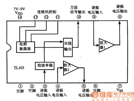
The following circuit illustrates the TL163 integrated circuit used in an ultrasonic remote control circuit diagram. Features include a detector, high-gain amplifier, and low-frequency capabilities. The TL163 integrated circuit serves as a pivotal component in ultrasonic remote control applications, facilitating...