
DTMF Receiver IC MT8870 Tester
The Motorola MT8870 DTMF receiver IC is designed to efficiently decode dual-tone multi-frequency signals generated by telephone keypads. The IC integrates a digital signal processing architecture that converts the analog tone pairs into binary outputs, which can be further interfaced with microcontrollers or other digital systems. The device operates by detecting the frequency components of the incoming signals, where each key on the keypad corresponds to a unique combination of two frequencies.
In practical applications, the circuit can be enhanced with features such as debounce logic to ensure that only valid key presses are registered, reducing erroneous outputs caused by noise or signal fluctuations. The use of high-quality capacitors and resistors in the circuit design is crucial for maintaining signal integrity and achieving reliable performance in various environments.
Furthermore, the implementation of transient protection using zener diodes not only safeguards the IC from voltage spikes but also enhances the longevity and reliability of the entire circuit. This is particularly important in communication systems where signal integrity and device protection are paramount.
In summary, the MT8870 DTMF receiver IC serves as a vital component in modern telecommunication systems, enabling efficient tone detection and decoding, while the accompanying tester circuit provides a practical solution for validating the functionality of the IC in both development and manufacturing settings.Today, most telephone equipment use a DTMF receiver IC. One common DTMF receiver IC is the Motorola MT8870 that is widely used in electronic communications circuits. The MT8870 is an 18-pin IC. It is used in telephones and a variety of other applications. When a proper output is not obtained in projects using this IC, engineers or technicians need to test this IC separately. A quick testing of this IC could save a lot of time in research labs and manufacturing industries of communication instruments. Here`s a small and handy tester circuit for the DTMF IC. It can be assembled on a multipurpose PCB with an 18-pin IC base. One can also test the IC on a simple breadboard. For optimum working of telephone equipment, the DTMF receiver must be designed to recognise a valid tone pair greater than 40 ms in duration and to accept successive digit tone-pairs that are greater than 40 ms apart.
However, for other applications like remote controls and radio communications, the tone duration may differ due to noise considerations. Therefore, by adding an extra resistor and steering diode the tone duration can be set to different values.
The circuit is configured in balanced-line mode. To reject common-mode noise signals, a balanced differential amplifier input is used. The circuit also provides an excellent bridging interface across a properly terminated telephone line. Transient protection may be achieved by splitting the input resistors and inserting zener diodes (ZD1 and ZD2) to achieve voltage clamping.
This allows the transient energy to be dissipated in the resistors and diodes, and limits the maximum voltage that may appear at the inputs. Whenever you press any key on your local telephone keypad, the delayed steering (Std) output of the IC goes high on receiving the tone-pair, causing LED5 (connected to pin 15 of IC via resistor R15) to glow.
It will be high for a duration depending on the values of capacitor and resistors at pins 16 and 17. The optional circuit shown within dotted line is used for guard time adjustment. The LEDs connected via resistors R11 to R14 at pins 11 through 14, respectively, indicate the output of the IC. The tone-pair DTMF (dual-tone multi-frequency) generated by pressing the telephone button is converted into binary values internally in the IC.
The binary values are indicated by glowing of LEDs at the output pins of the IC. LED1 represents the lowest significant bit (LSB) and LED4 represents the most significant bit (MSB). So, when you dial a number, say, 5, LED1 and LED3 will glow, which is equal to 0101. Similarly, for every other number dialled on your telephone, the corresponding LEDs will glow. Thus, a non-defective IC should indicate proper binary values corresponding to the decimal number pressed on your telephone keypad. Keys A, B, C, and D on the telephonekeypad are used for special signalling and are not available on standard pushbutton telephone keypads.
Pin 5 of the IC is pulled down to ground through resistor R8. Switch on auxiliary switch S2. Now the high logic at pin 5 enables the detection of tones representing characters A, B, C, and D. 🔗 External reference
Related Circuits
The integrated circuit (IC) tester featured on this website is specifically designed for the LM555 timer IC. This circuit is utilized for testing the functionality of the timer IC, and it includes a circuit diagram along with techniques for...
Many audio systems consist of separate units, and due to economic reasons, only the amplifier is equipped with a remote control receiver module. Control signals are then transmitted to other units using patch cables. For instance, the tuner and...

This is the circuit diagram of a mini AM radio receiver. All general-purpose transistors should work in this circuit; BC549 transistors can be used. The circuit utilizes a compact three-transistor regenerative receiver with fixed components. The mini AM radio receiver...
The three-transistor circuit costs less than $10 to build, uses commonly available components, and consumes less than 10 mA from a single 9V battery. By winding coil L1 as shown, the circuit can receive signals in the 5 to...
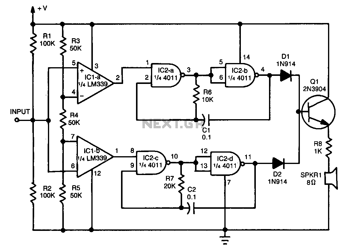
This tester provides an audible indication of the logic level of the signal presented to its input. A logic high is indicated by a high tone, a logic low is indicated by a low tone, and oscillation is indicated...
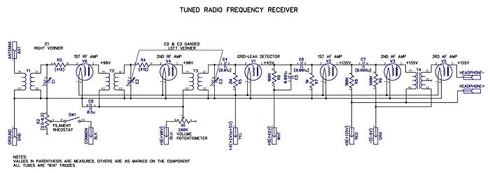
Tuned radio frequency receiver. A radio receiver consisting of several amplifier stages that... A tuned radio frequency (TRF) receiver is a type of radio receiver that utilizes multiple amplification stages to enhance the reception of radio frequency signals. The design...