
IR Remote Control Receiver
This circuit is designed to facilitate remote control functionality for audio equipment that lacks built-in IR receiver capabilities. The use of an IR receiver module allows for the reception of infrared signals from a remote control, which can then be processed and transmitted to other audio units via patch cables. The circuit employs a dual-inverter configuration to ensure signal integrity and compatibility with various audio devices.
The first inverter serves as a buffer, addressing the high impedance output of the IR receiver module. This configuration is critical, as it prevents signal degradation and ensures that the subsequent inverter receives a robust signal for further processing. The active low output from the IR receiver necessitates the use of the first inverter to produce a non-inverted signal, which is then inverted again by the second inverter, providing flexibility in output signal selection through jumper JP1.
To protect the circuit and the connected audio equipment, resistor R2 is incorporated to safeguard against short circuits and potential overloads, especially when interfacing with devices that operate at lower voltage levels, such as 3 V logic circuits. The inclusion of R1 and C1 helps to filter out any transient voltage spikes that may occur in the power supply line, enhancing the reliability of the circuit during operation.
Power consumption is minimal, allowing for the use of compact battery solutions. The choice of battery type can vary based on usage patterns; rechargeable NiMH batteries offer environmental benefits and long-term cost savings, while alkaline batteries provide a longer operational lifespan if the circuit is not frequently powered on and off. Overall, this circuit provides a practical solution for integrating remote control capabilities into standalone audio components, enhancing user convenience and system functionality.With many audio systems consisting of separate units, you`ll oftennd that due to economic reasons only the amplifier has a remote control receiver module. The control signals are then sent to the other units using patch cables. The tuner and CD player, for example, won`t have a built-in receiver module. When the tuner from such a system is bou ght separately it can therefore not be used directly with a remote control, which is a big disadvantage in practice. The only way in which this can be accomplished is to connect an IR receiver to the input used by the patch cable.
And that is exactly what this circuit is for. In practice it is not always clear which signal should be used and what its polarity should be. However, it will most likely be a demodulated signal. For these reasons we`ve combined a standard IR receiver module and two inverters. The first inverter also functions as a buffer, since the output of the module has a high impedance. The output of the receiver module is active low, so therst inverter outputs a non-inverting signal. The second inverter inverts this signal again. Jumper JP1 is used to select which of the signals is presented at the output. R2 protects the output from short circuits or possible over-loading of the electronics in the equipment it`s driving (for example when the input circuit uses 3 V logic). R1/C1 suppress any possible supply spikes. Batteries are suitable for the power supply, because the circuit only takes about 1 mA. With a set of four rechargeable batteries with a capacity of 1800 mAh the circuit can function continuously for 2.
5 months. Four NiMH cells and a charger are therefore perfect for the power supply. If you can be sure that the circuit will always be switched off when not in use, you could also use three ordinary alkaline batteries (AA cells). Because of their slightly larger capacity they will probably last for about half a year. When making your choice you should of course keep in mind that recharge-ables are better for the environment.
🔗 External reference
Related Circuits
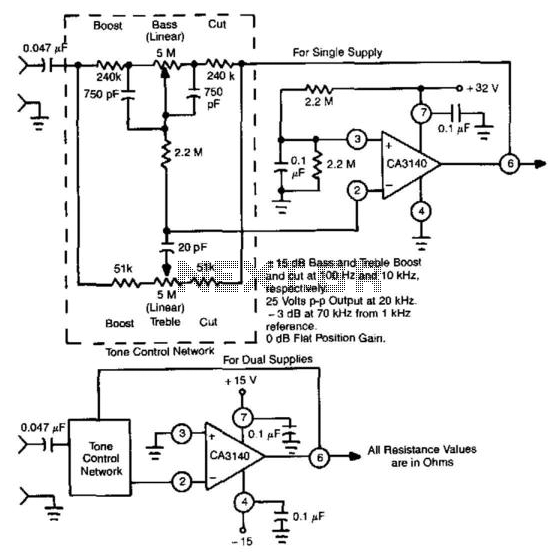
This circuit utilizes the high slew rate, high input impedance, and high output-voltage capability of the CA3140 BiMOS operational amplifier. It also offers mid-band unity gain using standard linear potentiometers. The circuit design leverages the characteristics of the CA3140 BiMOS...

This small device can be aimed at a television to jam the remote control signal. The circuit design is straightforward. A 555 timer is configured as an astable multivibrator operating at a frequency of approximately 38 kHz, which is...
To comprehend the interconnections between the following circuits, it is essential to first review the concept chapter. It is at the discretion of the user to select one or two of these circuits for personal development. The discussion begins...
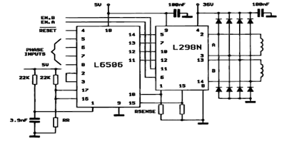
The following figure illustrates the control circuit for a two-phase bipolar stepper motor utilizing the current controller L6506. The L6506 integrated circuit generates the necessary signals to drive the inputs of the L298 bipolar stepper motor circuit driver. The circuit...
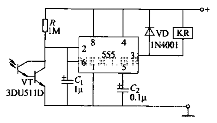
The circuit utilizes a Darlington-type phototransistor as the sensing element, which enhances sensitivity to low light levels, making it suitable for detecting reflected light signals. When the Darlington phototransistor is exposed to light, its resistance decreases, causing the voltage...
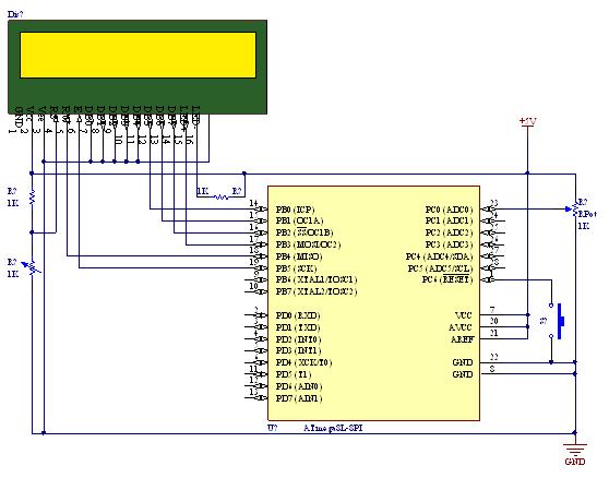
A straightforward tutorial on utilizing the ADC (Analog to Digital Converter) unit of the AVR microcontroller, demonstrated with the Atmega8, including a circuit diagram and code examples. The ADC unit in the Atmega8 microcontroller is a crucial component that allows...