
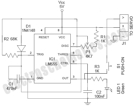
Timer IC tester LM555 tester

The LM555 timer IC is a versatile component widely used in various timing, delay, pulse generation, and oscillator applications. The IC tester circuit for the LM555 is structured to verify the operational integrity of the IC by applying specific input conditions and measuring the output response.
The schematic typically includes a power supply section, which provides the necessary voltage (usually between 4.5V and 15V) to the LM555. A series of test points are included in the circuit to connect the LM555 IC, allowing for easy insertion and removal. The circuit may also feature a switch to toggle between different modes of operation, such as monostable and astable configurations.
In the monostable mode, the tester circuit triggers the LM555 with a short pulse, and the output is monitored to ensure that it returns to a low state after a predetermined time delay. This delay can be adjusted using external resistors and capacitors connected to the IC.
In the astable mode, the circuit continuously oscillates between high and low states, producing a square wave output. The frequency and duty cycle of this output can be varied by changing the values of the resistors and capacitors in the circuit. The tester can include LED indicators to visually represent the output states, providing immediate feedback on the IC's functionality.
In addition to the basic testing capabilities, the circuit can be expanded with additional components, such as a frequency counter or an oscilloscope interface, to provide more detailed analysis of the output waveform characteristics. This comprehensive testing approach ensures that the LM555 timer IC is functioning correctly before being implemented in more complex electronic projects.The IC tester in this web site is specially designed for the timer IC LM555. this circuit is used for testing timer IC. circuit diagram and technique of various project . 🔗 External reference
Related Circuits
A servo is an error-sensing feedback control mechanism used to correct the performance of a system. A servo motor is a DC motor equipped with a servo mechanism. A servo motor is an electromechanical device that utilizes a closed-loop control...
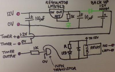
Most supermarkets today offer plug-in mains-powered digital programmable timers. These devices are designed to automatically turn lights on and off, activate washing machines while the user is away, and more. Prices start at around £5 ($10), and these products...

S2 is utilized to initiate timing. A transition from light to dark or dark to light halts this timer, depending on the configuration of S5. S3 provides a direct operating mode, bypassing the latch. IC3 and IC4 generate timing...
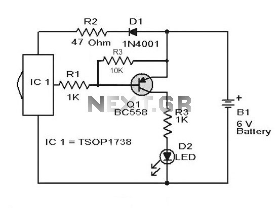
A simple remote control tester circuit with a diagram and schematic using the infrared sensor IC TSOP1738. An LED will blink when infrared waves fall on it, indicating the remote control is functioning. The remote control tester circuit utilizes the...
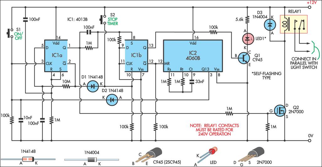
This 9-minute timer switch can be utilized to control lighting in a toilet or bathroom. The timer is activated by pressing switch S1 and deactivated by pressing S1 again. If the timer is not manually turned off, the light...
This circuit provides a visual 9-second delay using 10 LEDs before closing a 12-volt relay. When the reset switch is closed, the 4017 decade counter resets to the 0 count, illuminating the LED driven from pin 3. The 555...