
Dual cable (serial + USB) for Nikon coolpixes
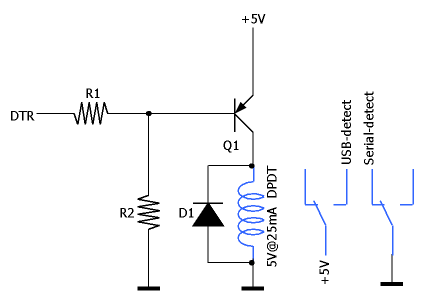
This circuit operates similarly to the previous design but utilizes a different approach. The relay is powered by a PNP transistor (Q1, such as the BC556), which is activated when DTR is negative or not connected. Conversely, if DTR is positive or the USB plug is not connected (leading to a lack of +5V power), Q1 and the relay remain off. With resistor R1 set to 10K and R2 to 22K, the DTR current remains low. Diode D1 can be a 1N4148. Measurements taken with a multimeter revealed that the resistance between the USB and serial port grounds in the computer is extremely low (under 0.1 ohm), suggesting they are interconnected within the computer, likely sharing the same power supply. The resistance between USB-GND and Serial-GND on the camera is also minimal. Considering all these grounds as a single electrical node, as inferred from the tests, allows for the simplification of the relay-based circuit to the configuration illustrated in figure 3.
The schematic involves a careful arrangement of components to ensure proper functionality and isolation between the USB and serial interfaces. The optocoupler serves as a critical element, providing electrical isolation while allowing signal transfer. The choice of a sensitive optocoupler is paramount, as it ensures that the small DTR current is sufficient to activate the optocoupler without exceeding the current limits of the serial port. The inclusion of the protection diode (D1) is essential to safeguard the optocoupler's LED from reverse voltage that could occur when DTR is not active.
The relay configuration, while unconventional, allows for flexibility in switching between USB and serial modes. The use of two parallel relays compensates for the unusual contact arrangement of the primary relay, ensuring reliable operation. The activation of the relay through the PNP transistor (Q1) adds a layer of control, permitting the circuit to respond dynamically to the DTR signal and the presence of a USB connection.
Resistors R1 and R2 are chosen to limit the current through the DTR line, ensuring that the circuit operates within safe parameters. The low resistance measurement between USB-GND and Serial-GND indicates a robust grounding scheme within the system, which is crucial for minimizing noise and ensuring signal integrity. This design demonstrates a thoughtful approach to interfacing USB and serial communications, emphasizing electrical isolation, current management, and the importance of reliable connections within the circuit.To assure that USB and serial segments are electrically isolated, we used an optocoupler (U1). The LED section of U1 is driven directly by DTR, so we should select a very sensitive optocoupler to prevent too much current flow from DTR (which is usually very limited, implementation-dependent; around 3 mA max. if we don't want to push the serial port to its limits). D1 protects the LED when DTR is negative. The NPN transistor section of U1 drives a PNP transistor which in turn operates a electromechanical relay.
This relay has three associated contacts: two normally open and one normally closed. This is a weird configuration for a commercial relay, so you will have to use two relays working in parallel instead. When the relay is idle, USB-detect and USB-GND are disconnected, while Serial-detect and Serial-GND are connected to the computer serial port ground, so the dual cable is in serial mode.
When the relay is activated, USB-detect is connected to +5V and USB-GND is connected to the computer USB port ground, so the cable is in USB mode. This circuit behaves the same as the previous one, but it is completely different. Now the relay is powered by a PNP transistor (Q1, for example, a BC556) which is on when DTR is negative or not connected. If DTR is positive or the USB plug is not connected (and hence there is no +5V power in the circuit), Q1 and the relay are off.
With R1 set to 10K and R2 to 22K, DTR current is small. D1 can be a 1N4148. Using a multimeter, we measured the resistance between the USB and serial port grounds in my computer, and it turns out to be extremely low (under 0.1 ohm), so we assumed that they are connected together inside the computer, as one can expect because they are likely to share the computer power supply. The resistance between USB-GND and Serial-GND on the camera is also very low. If we consider all these grounds as the same electrical node (as it is deduced from these tests), the relay-based circuit can be simplified to the one depicted in figure 3.
🔗 External reference
Related Circuits

The 78W series voltage regulators are designed to handle an input voltage of approximately 35V, while the 24V type can withstand up to 40V. It should be noted that these regulators will not operate effectively with a significant input-output...
This is a microphone preamplifier designed for compatibility with a SoundBlaster AWE 64 sound card. It is also suitable for any compatible tag or PC audio input that provides a 5 Volt supply through a 2.2kΩ current-limiting resistor located...
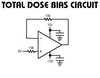
The RH1078M is a micropower dual operational amplifier in a standard 8-pin configuration. This device is optimized for single supply operation at 5V, with specifications also available for ±15V. Linear Technology provides numerous demo boards at no cost to...
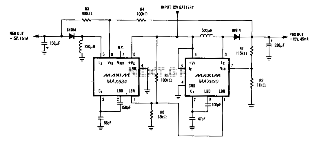
A MAX634 inverting regulator is combined with a MAX630 to provide a dual tracking ±15 V output from a 12-V battery. The reference for the -15 V output is derived from the positive output via resistors R3 and R4....
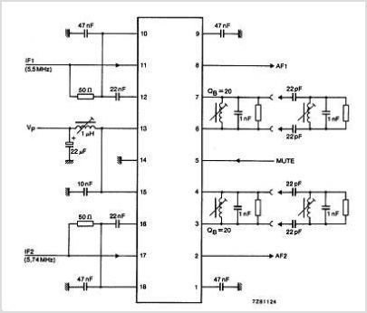
The TDA3567 is a monolithic integrated decoder designed for the NTSC color television standards. It incorporates all the necessary functions for the demodulation of NTSC signals. Additionally, it features a luminance amplifier and an RGB matrix amplifier. These amplifiers...
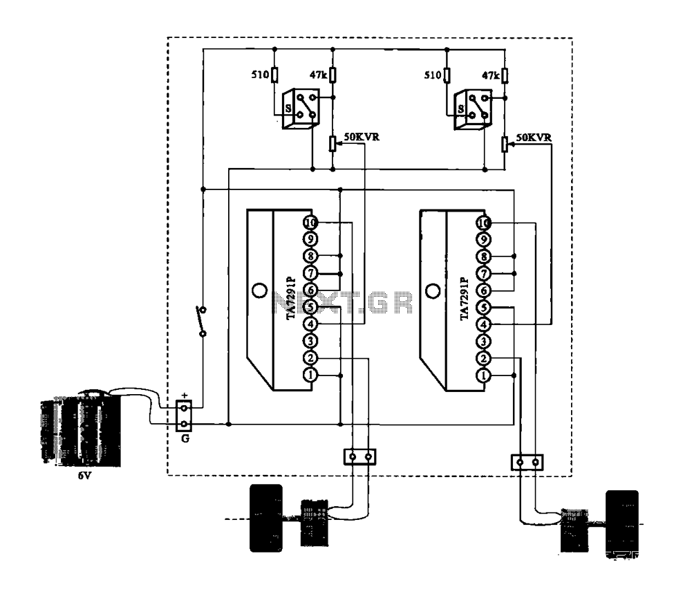
A dual motor drive circuit for automatic tracking consists of two motors that are part of a car structure, which operates based on the principles of a double motor drive system. The dual motor drive circuit is designed to facilitate...