
Dual motor drive circuit

The dual motor drive circuit is designed to facilitate automatic tracking functionality in robotic or automated vehicles, such as cars that follow a designated path. The circuit typically includes two DC motors, each responsible for driving one side of the vehicle. By varying the speed and direction of these motors, the vehicle can navigate along a predefined route, which is often marked by a white line or similar guiding feature.
In this configuration, the motors are controlled using a microcontroller that processes input signals from sensors, such as infrared or optical sensors, positioned at the front of the vehicle. These sensors detect the presence of the white line and provide feedback to the microcontroller, which adjusts the motor speeds accordingly to maintain alignment with the line.
The circuit may also incorporate additional components such as motor drivers, which serve to amplify the control signals from the microcontroller to a level sufficient to drive the motors. Power supply considerations are crucial, as the motors require adequate voltage and current to operate effectively. Therefore, a suitable power source, such as batteries or a power adapter, must be integrated into the design.
Furthermore, safety features, such as overcurrent protection and thermal shutdown mechanisms, can be included to prevent damage to the motors and circuit components during operation. The overall design emphasizes efficiency, reliability, and responsiveness, allowing for smooth and precise movement of the vehicle along its tracking path. This dual motor drive circuit serves as a foundational element in various applications, including robotics, automation, and educational projects.Dual motor drive circuit Automatic tracking shows are constituted by two motors (white line) Cars structure, principle and double motor drive circuit.
Related Circuits
A series of shunts and multipliers selected by a switch can be utilized in conjunction with a single basic meter to create a multirange instrument, commonly referred to as a multimeter. This device is capable of measuring voltage, current,...
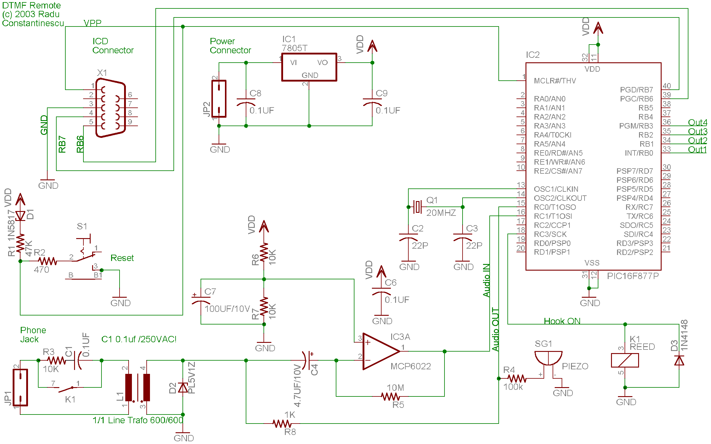
A telephone remote control system allows users to perform various functions remotely using their phone. This system automates complex tasks, simplifying the development and operation of telephone systems. The telephone remote control system is designed to enhance user interaction with...
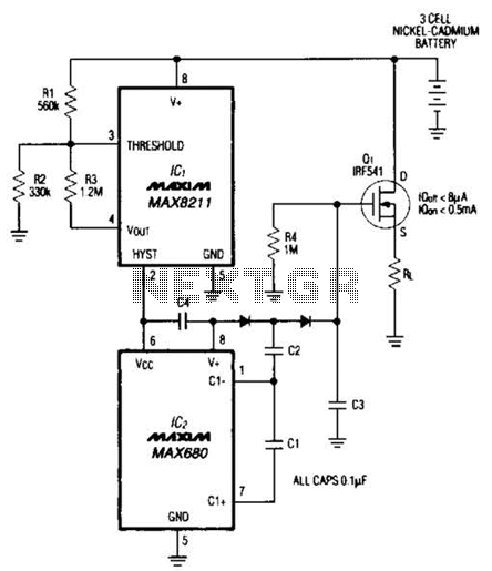
Deep discharge can damage a rechargeable battery. By disconnecting the battery from its load, this circuit halts battery discharge at a predetermined level of declining terminal voltage. Transistor Q1 acts as the switch. The overall circuit draws about 500µA...
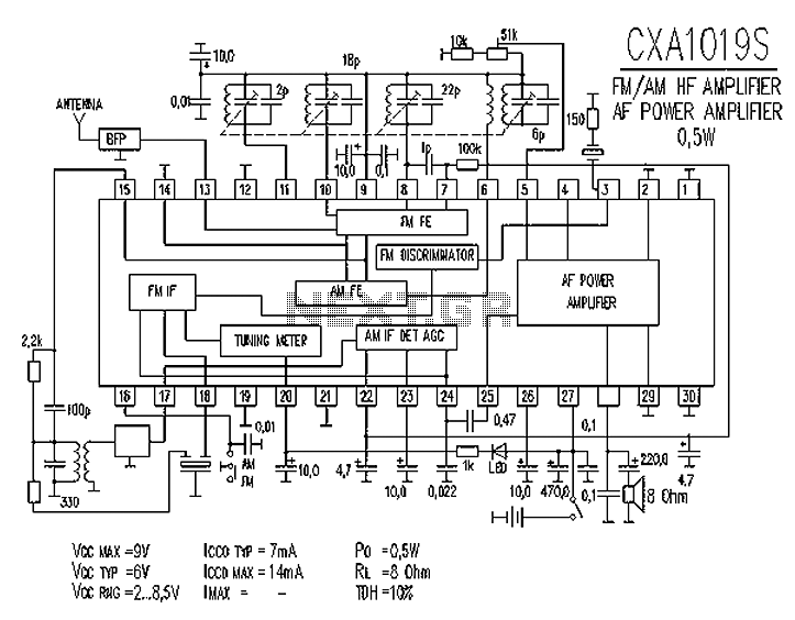
CXA1019 is a high-performance, high-sensitivity FM/AM radio special manifold developed by Sony, Japan. The CXA1019 features high integration, which includes an FM/AM tuner circuit, a mixer circuit, a mute circuit, an amplifier circuit (power output of 0.5 to 1W),...
As shown in the generator start battery automatic monitor circuit diagram. The generator start battery automatic monitor circuit is designed to oversee the battery's status during generator operation. This circuit ensures that the battery remains charged and functional, preventing premature...
PID-Control with 68HC11. STEPPER CONTROL. 68HC11 read encoder. High accuracy RPM-measurement with 68HC11. The encoder is connected to PORTA PA0 and PA1. The board must be in BOOTSTRAP MODE (tested with Loggyboard). The circuit utilizes a 68HC11 microcontroller for implementing...