
12V DC Dual Power Supply Circuit with IC 7812&7912

The circuit utilizes two transformers for voltage regulation and transformation, with the first transformer stepping down the AC input to a lower AC voltage. The rectification process converts the AC voltage to DC, which is then filtered to smooth out fluctuations. The voltage regulators (IC6 and IC7) play a critical role in maintaining stable output voltages for various components in the system, ensuring that sensitive devices such as the DPM system and operational amplifiers receive the appropriate voltage levels for optimal performance.
The use of Zener diodes for generating the ±12V supplies is a common practice in electronic design, as they provide a simple and effective means of voltage regulation. However, care must be taken to ensure that the power dissipation across these diodes is within acceptable limits to prevent thermal issues.
The quadruple voltage multiplier circuit is an efficient method for achieving high voltage outputs from a lower voltage source. This configuration is particularly useful in applications where high voltages are necessary for testing components or powering specific circuits. The careful design of the rectification and filtering stages ensures that the output voltage is stable and free from significant ripple, which is crucial for the reliable operation of electronic devices.
Overall, this circuit design demonstrates a comprehensive approach to voltage regulation and transformation, employing multiple stages of rectification, filtering, and regulation to achieve the desired output voltages for various applications.Regulators Series 78W to kind of stay 8V input voltage of about 35V, while the type 24v withstand 40V. Of course, of course, that regulators will not work with such an important input differential output as it would lead to excessive power is dispersed.
All controllers will deliver the 78W series 1000mA current maximum expected input differential voltage output of less than 7V. Otherwise, too diffuse power, thereby bringing the fire extinguished. Two transformers were used to step voltage 230-250V AC input power. It manufactures power transformers 6-0-6V secondary terminals. This output is fed into the rectifier and filter capacitor. Filtered IC6 that served 3-pin voltage regulator that provides a regulated output + 5V. It is used to enable the DPM system. It also comes as the network voltage source temperature accuracy. Other manufactures transformers with a capacity of 12-0-12V at its secondary terminals. The center was established as a fountain in the previous case. The other two secondary terminals are fed bridge rectifier constructed using diodes. Output recovered is filtered using a capacitor C5 and C6 for food and IC7 IC. In-8 IC7, which are 3-pin regulators provide output voltage of ± 8V. These two voltages are signal generator. TO-8V power source is applied to the temperature of the network, and the reference voltage. It is also necessary to +12 V and-12V supplies for the implementation of operational amplifiers. This can be easily done using a 12V zener diodes. The output of bridge rectifier is attached to the +12 V and-12V, respectively, using two zener diodes. In the zener output is fed to the terminals of the operational amplifier supply. For supply for operational amplifiers must not be very effective in regulating + 12V, the use of Zener diodes be costly.
For the testing of electronic components voltage above 50 V is required. This can be achieved through quadruple the chain tension. It consists of four diodes and four electrolytic capacitors. Unreasonable Administration Secondary 12-0-12V is connected to quadruple string. Quadrupled output of the circuit is 68V to ground. Be the first of your friends to get free diy electronics projects, circuits diagrams, hacks, mods, gadgets & gizmo automatically each time we publish. Your email address & privacy are safe with us ! 🔗 External reference
Related Circuits
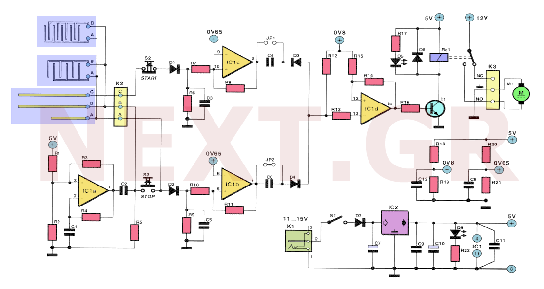
Often, for various reasons, individuals forget or are unable to water the plants in their homes. Many humidity sensor units merely alert users with a beeping sound or a flashing light when the pot requires watering. However, what if...

This circuit was first introduced by Signetics Corporation as the SE555/NE555 around 1971. Pin connections and functions are as follows: Pin 1 (Ground) is the most negative supply potential of the device, typically connected to circuit common when powered...
This project is a versatile power supply designed for use in electronics, capable of addressing various supply issues encountered in typical electronics workshops. It offers a continuously variable output voltage range from 3 V to 30 V, with a...
The double-ended working core square wave inverter transformer area product formula Bm represents the maximum magnetic flux. The primary side of the transformer features switches S1 and S2 in parallel with IRF32055. This parallel configuration is primarily due to...
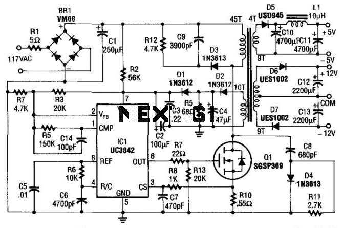
This power supply utilizes an SGS-Thomson UC3842 integrated circuit in an off-line flyback regulator configuration, delivering +5 V at 4 A and ±12 V at 300 mA. This design allows for the use of a compact high-frequency (50 kHz)...
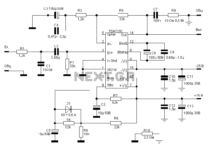
The TDA7293, produced by the ST (SGS-THOMSON) company, is a high-power, high-voltage DMOS high-fidelity amplifier integrated circuit (IC) with a rated output power of 100W. It operates at a maximum voltage of 120V. The key specifications include a dual...