
Pulse coincidence detector
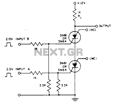
The described circuit operates on the principle of detecting simultaneous input signals to control the output across a resistor. The primary component, a silicon-controlled switch (SCS), is a four-layer semiconductor device that can be turned on and off by applying appropriate gate signals. In this configuration, the SCS is used to manage the flow of current through resistor Rl based on the coincidence of two distinct input signals.
When input A and a secondary input with an amplitude of 2 to 3 volts are applied simultaneously, a voltage is developed across Rl. The critical aspect of this design is the timing; the overlap of the two inputs must be less than 1 microsecond to ensure reliable triggering of the SCS. This rapid response time is essential for applications requiring fast switching.
Additionally, the circuit employs gates G^ to detect the coincidence of negative inputs, which is a modification from the use of gates Gc. This adaptation allows for enhanced performance in specific applications where negative signal detection is crucial. The complementary SCR configuration of the SCS provides flexibility and improved control over the output, allowing for greater efficiency in managing the current flow through the circuit.
Overall, this circuit design effectively leverages the properties of the SCS and logic gates to achieve precise control of voltage across Rl, making it suitable for various electronic applications that require rapid response to input conditions.Unless inputs A and (2- to 3-V amplitude) occur simultaneously no voltage exists across Rl. Less than 1 microsecond overlap is sufficient to trigger the scs. Coincidence of negative inputs is detected with gates G^ instead of Gc by using the scs in a complementary SCR configuration. 🔗 External reference
Related Circuits
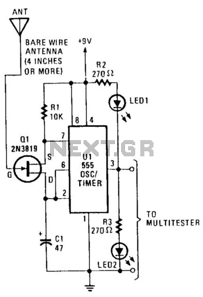
This circuit detects the presence of electrostatic fields by using a Field Effect Transistor (FET) to alter the flash rate of two Light Emitting Diodes (LEDs). The FET is installed in the timing circuit and causes a change in...
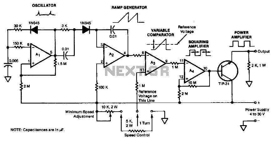
The quad operational amplifier circuit provides a pulse width modulation control ranging from 0 to 100 percent. The controller utilizes an LM3900 and operates with a single supply voltage between 4 to 30 V. A 1 kHz oscillator amplifier,...
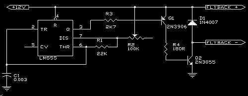
A 555 is used as an oscillator, optimally around 15.76KHz (in North America). Power pins on the chip (pin 1 to ground, pin 8 to +12V) are not shown on the diagram. The output from the 555 is then...
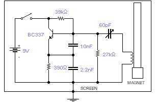
This basic oscillator will detect the Earth magnetic field. The ferrite rod and coil are taken from an old Medium Wave receiver and a small magnet is glued at one end. Tune to a medium wave commercial station until...
This article explains the principle of the Audison LR604XR amplifier. The principle is straightforward; it is recommended to combine the text with a careful reading of the complete schematic. To fully understand this principle, it is advisable to review...
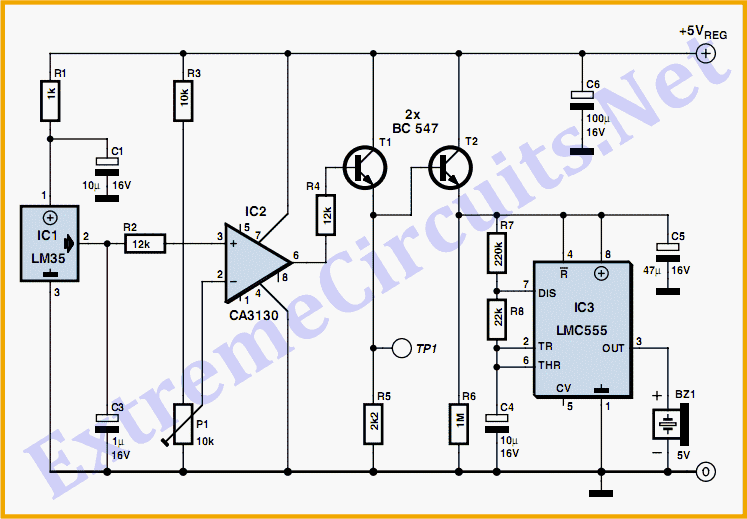
At the core of this circuit is a precision integrated temperature sensor, the LM35 (IC1), which provides a linear and directly proportional output related to temperature measurements. The LM35 temperature sensor is a well-known device used for temperature sensing applications....