
Dual drive ICs 10LED level meter circuit
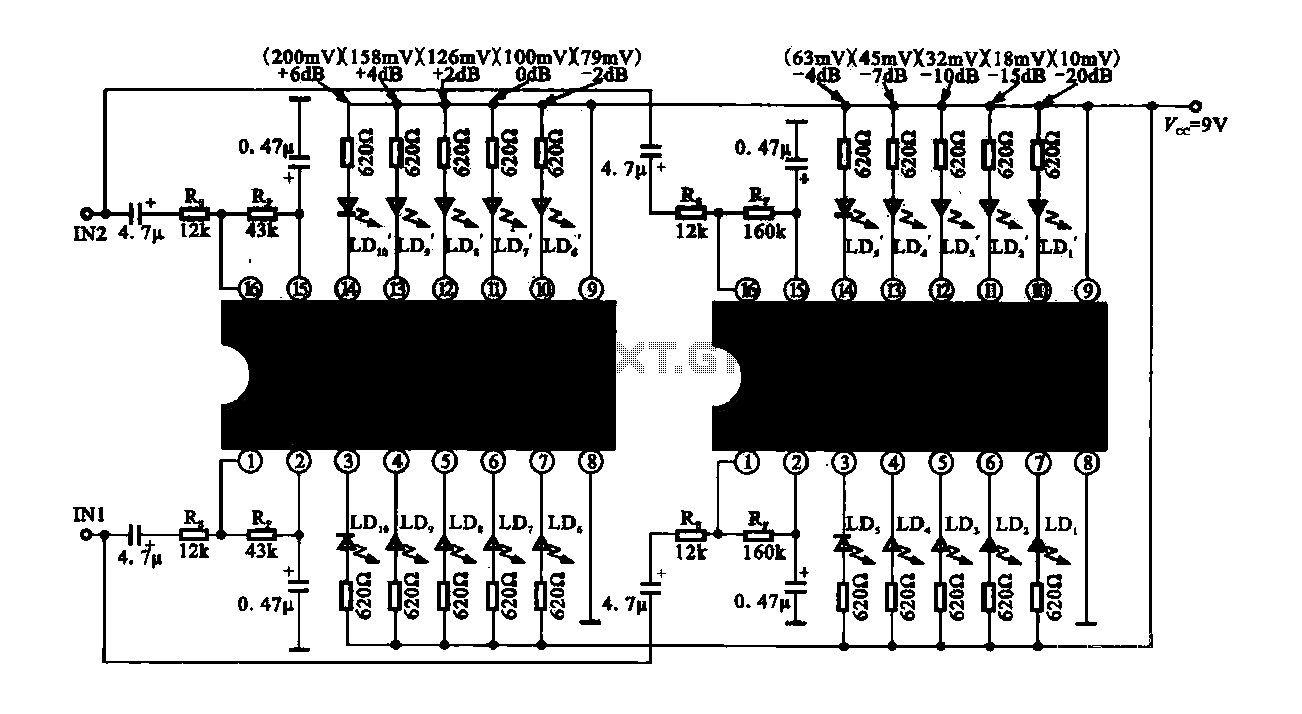
The 10 LED level meter circuit is designed to provide a visual representation of voltage levels through the illumination of LEDs. In this circuit, the dual drive ICs play a crucial role in controlling the LEDs based on the input voltage levels. The TLM8101 is a versatile driver capable of managing multiple LEDs, making it suitable for this application.
The circuit typically operates by receiving an analog input voltage, which is then compared against predefined thresholds. As the input voltage varies, the corresponding LEDs illuminate sequentially, indicating the level of the input signal. Each LED corresponds to a specific range of voltage, and the dual drive configuration allows for more efficient control and reduced power consumption.
The TLM8101 ICs can be configured for different driving capabilities, allowing flexibility in the number of LEDs that can be lit simultaneously. The design may include resistors to limit the current through the LEDs, ensuring they operate within safe limits. Additionally, capacitors may be used for smoothing any fluctuations in the input signal, providing a more stable output.
For implementation, it is essential to consider the power supply requirements of the TLM8101 and the forward voltage ratings of the LEDs used. Proper heat dissipation methods should also be applied to prevent overheating during operation. Overall, this dual drive LED level meter circuit is an effective solution for visualizing voltage levels in various electronic applications.Dual drive ICs 10LED level meter circuit Dual-drive IC is shown in the IO LED level meter circuit, the figure of two TLM8101 driver IC can also be used instead.
Related Circuits
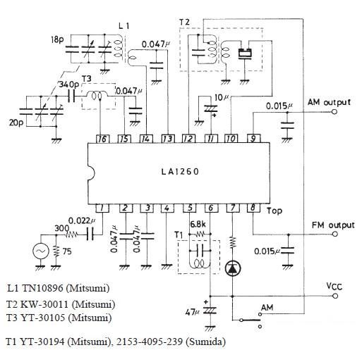
This FM IF MW radio receiver circuit schematic utilizes the LA1260 integrated circuit (IC), which is suitable for AM and FM radio receiver electronic projects. The LA1260 incorporates numerous functions and features essential for radio receiver applications, including a...
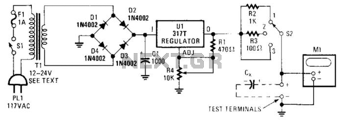
Sometimes electrolytic capacitors that are stored for a period may exhibit high leakage currents. Before utilizing these capacitors, it may be necessary to reform them. This power supply can be employed for the reforming process. Adjust resistor R4 according...
The purpose of this circuit is to animate shop windows using a capacitive sensor positioned behind a postcard-like banner. The card is placed against the glass inside the shop window, allowing visitors to activate the relay by placing their...
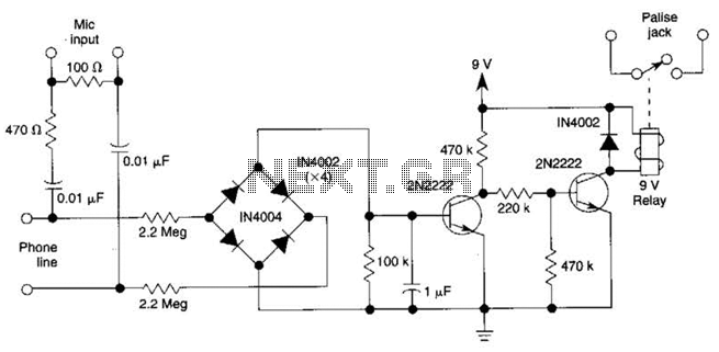
The DC voltage on a telephone line typically ranges from 45 to 50 V when on-hook and drops to around 6 V when off-hook. This circuit utilizes the voltage drop to activate a relay, which in turn controls a...
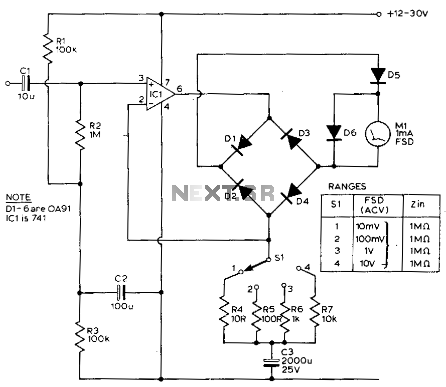
This circuit exhibits a flat frequency response from 8 Hz to 50 kHz, maintaining a -3 dB level at the 10 mV range. Furthermore, while the upper frequency limit remains consistent across less sensitive ranges, the lower frequency limit...
This circuit allows the use of an inexpensive loudspeaker as a microphone. Sound waves that reach the speaker cone create fluctuations in the voice coil. The movement of the voice coil within the speaker's magnetic field generates a small...
Warning: include(partials/cookie-banner.php): Failed to open stream: Permission denied in /var/www/html/nextgr/view-circuit.php on line 713
Warning: include(): Failed opening 'partials/cookie-banner.php' for inclusion (include_path='.:/usr/share/php') in /var/www/html/nextgr/view-circuit.php on line 713