
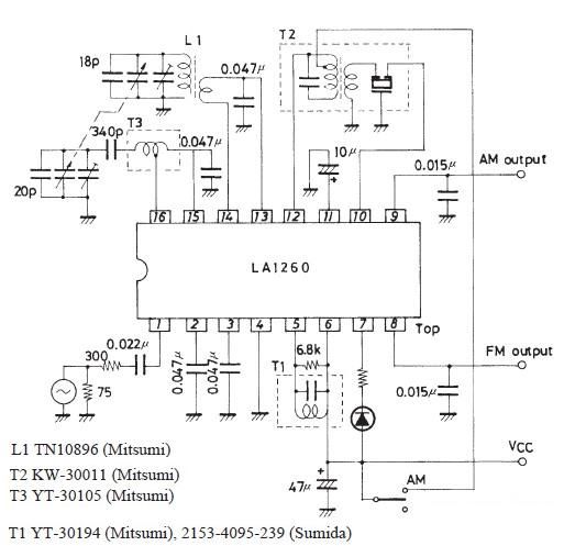
FM IF MW radio receiver circuit using LA1260 integrated circuit
The LA1260 IC is designed with a variety of integrated functions that facilitate the construction of efficient radio receivers. The high S/N ratios for both FM and AM ensure clear audio output, making it suitable for various applications. The low-level AM oscillator with ALC is particularly advantageous for maintaining consistent performance across different signal strengths, thereby enhancing the receiver's sensitivity and selectivity.
In terms of circuit design, careful attention must be paid to the layout of the components. The separation of the AM local oscillation parts, including the coil and antenna circuits, is crucial for minimizing interference and ensuring optimal signal processing. This design consideration helps to reduce unwanted noise and maintain the integrity of the received signals.
The inclusion of an on-chip LED tuning indicator provides a visual feedback mechanism, allowing users to easily identify the tuning status of the receiver. This feature enhances usability, particularly in mobile or portable applications where quick adjustments may be necessary.
The FM/AM selector, also integrated within the LA1260, simplifies the design by allowing a single IC to handle both types of modulation, thus reducing the overall component count and complexity of the circuit. The independent output pins for FM and AM further enhance versatility, enabling the use of separate processing stages for each modulation type if desired.
For power supply considerations, the ability of the LA1260 to operate over a range of 3 to 8 volts DC provides flexibility in design, allowing it to be powered by various sources, including batteries or regulated power supplies. This adaptability makes the LA1260 a valuable component in the design of portable radio receivers, where power efficiency and size constraints are often critical factors.
Overall, the LA1260 IC presents a comprehensive solution for AM and FM radio receiver projects, combining high performance with user-friendly features and flexible design options.As you can see in this FM IF MW radio receiver circuit schematic the LA1260 ic can be used in AM FM radio receiver electronic projects. LA1260 has integrated in the package many functions and features that are needed for radio receiver applications.
high S/N : FM 81dB, AM 53dB ;low-level AM oscillator with ALC MW 130mV SW 70 mV to 90 mV (7MHz) (2 4MHz) ;less AM whistle interference : whistle 1% at input 100dB/m. ;on-chip LED tuning indicator driver ;on-chip FM/AM selector; independent FM/AM output pins. The AM local oscillation parts, AM local oscillation coil, and antenna circuit parts such as bar antenna must be separated from each other as far as possible to prevent Qs from worsening. Pin 16 (AM oscillation injection pin) and pin 14 (RF input pin) must be separated from each other. The recommended power supply for this radio receiver circuit is 4. 5 volt DC, but the LA1260 ic accepts an input voltage range from 3 to 8 volts DC. 🔗 External reference
Related Circuits
This LED flasher circuit is a classic two-transistor flip-flop. It is a popular circuit often built by beginners in the electronics hobby. The schematic diagram of this well-known LED flasher circuit includes two transistors, two capacitors, four resistors, and...
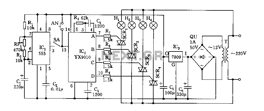
Fantasy lights offer wonderful changes suitable for storage, dance halls, or family holiday decorations. The control circuit is depicted here, which includes a multivibrator control circuit, a thyristor trigger circuit, and a step-down power supply circuit. The AC step-down...
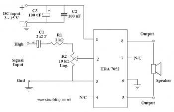
This is an audio amplifier circuit that uses the TDA7052 as the main component, along with five additional components to support its operation. The ideal supply voltage for this circuit is approximately 6-12V, and it does not require a...
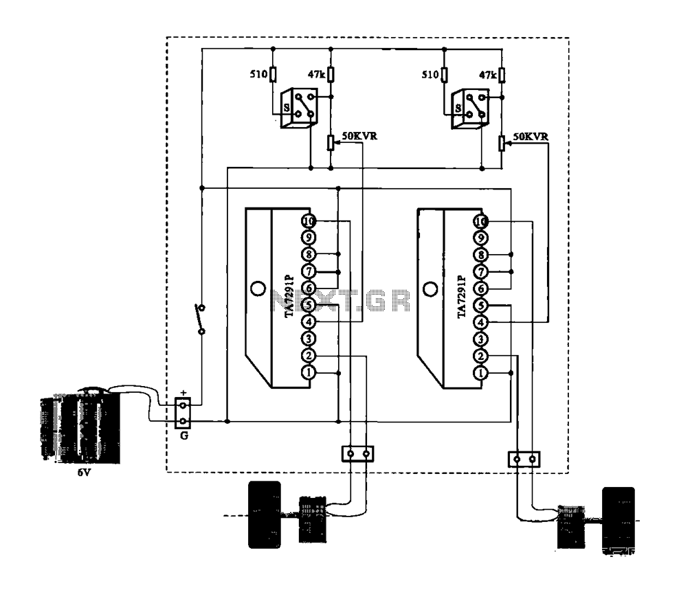
A dual motor drive circuit for automatic tracking consists of two motors that are part of a car structure, which operates based on the principles of a double motor drive system. The dual motor drive circuit is designed to facilitate...
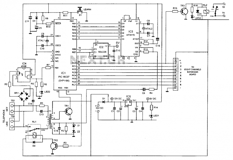
This device enables remote control of various appliances (up to eight with suitable add-on expansion boards) such as lights, water heaters, air conditioning, plant watering systems, alarms, etc., via a relay. It allows users to perform actions such as...
The controller circuit illustrated in Figure 15-24 consists of a switch-type Hall integrated circuit DN838 and an astable multivibrator, which is based on the 555 timer IC. This circuit is suitable for various applications, including automatic door opening, delay...
Warning: include(partials/cookie-banner.php): Failed to open stream: Permission denied in /var/www/html/nextgr/view-circuit.php on line 713
Warning: include(): Failed opening 'partials/cookie-banner.php' for inclusion (include_path='.:/usr/share/php') in /var/www/html/nextgr/view-circuit.php on line 713