
Telephone Call Recording Circuit Circuit
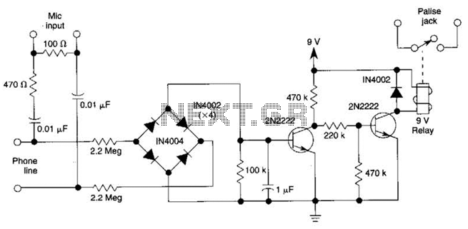
The described circuit operates by leveraging the characteristics of the telephone line's DC voltage. When the telephone is in the on-hook state, the voltage remains high, typically between 45 and 50 volts. In this condition, the relay remains deactivated, preventing any current flow to the cassette tape recorder. However, when the telephone goes off-hook, the voltage significantly drops to approximately 6 volts. This voltage drop is the critical factor that triggers the relay to activate.
The relay serves as an intermediary switch that allows the low-voltage signal to control the operation of the cassette tape recorder. Upon activation, the relay closes its contacts, allowing power to flow to the cassette tape recorder, thus enabling it to start recording or playback audio as required.
Additionally, the circuit incorporates an audio extraction network designed to capture the audio signals from the telephone line. This network typically consists of passive components such as resistors and capacitors, which filter and condition the audio signal before routing it to the microphone input of the cassette tape recorder. The audio quality and clarity are maintained through careful selection of these components, ensuring that the recorded audio accurately represents the original sound captured from the telephone line.
Overall, this circuit effectively combines telecommunication and audio recording technologies, providing a practical solution for capturing audio directly from telephone conversations. The dc voltage present on a telephone line is usually around 45 to 50 V on-hook and 6 V off-hook. This circuit uses This drop in voltage to activate a relay. The relay controls a cassette tapeTecorder. Audio is taken off through a network to the microphone input of the cassette. 🔗 External reference
Related Circuits
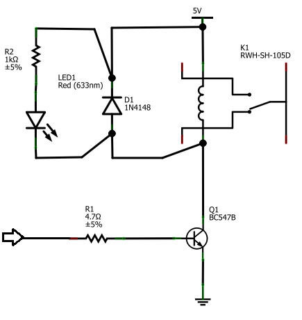
The BC547B transistor has a collector-base voltage (Vcbo) of 50V, a collector-emitter voltage (Vceo) of 45V, and an emitter-base voltage (Vebo) of 6V. In contrast, the BC548 transistor in the original circuit has a Vcbo of 30V, a Vceo...
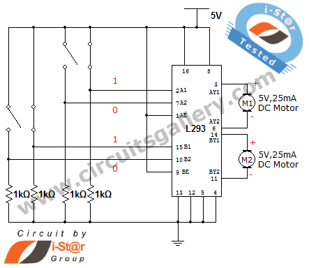
How can a DC motor be rotated in clockwise and counterclockwise directions? This is a common question posed by many robotics beginners. DC motor driver circuits are essential components in robotics workshops. The L293D IC is frequently utilized for...
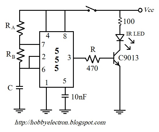
The remote control circuit comprises two main components: a transmitter and a receiver. The transmitter circuit is controlled by an NE555 integrated circuit (IC), while the receiver operates based on the frequency of the signal emitted by the transmitter....
The LED flasher circuits below operate on a single 1.5 volt battery. The circuit on the upper right uses the popular LM3909 LED flasher IC and requires only a timing capacitor and LED. The top left circuit, designed by...
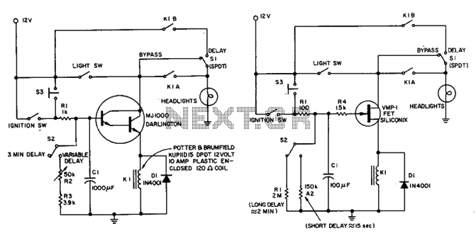
This circuit maintains the headlights of an automobile in an on state temporarily. It also ensures that the lights turn off automatically, even if the user forgets to switch them off manually. The shut-off delay is activated only when...
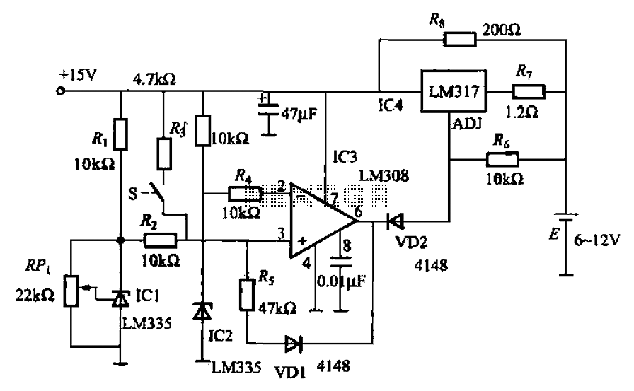
When fast charging a nickel-cadmium battery, the temperature control circuit, as illustrated in the accompanying figure, is designed to monitor the battery temperature to regulate the charging current. The circuit consists of Icl to IC3, which forms the temperature...
Warning: include(partials/cookie-banner.php): Failed to open stream: Permission denied in /var/www/html/nextgr/view-circuit.php on line 713
Warning: include(): Failed opening 'partials/cookie-banner.php' for inclusion (include_path='.:/usr/share/php') in /var/www/html/nextgr/view-circuit.php on line 713