
Dual Input-Combining Stereo Line Amplifier
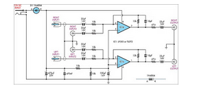
The circuit is designed to facilitate the merging of two independent line-level stereo signals into a single output while preserving the stereo characteristics. This process is essential in applications where multiple audio sources need to be managed without the complexity of manually switching between them.
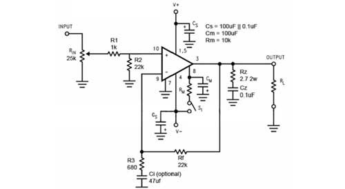
The core of the circuit typically involves operational amplifiers configured as summing amplifiers. Each line-level input signal is fed into the non-inverting terminals of the op-amps, which are configured to sum the signals. The output from each op-amp represents the combined left (L) and right (R) channels.
To ensure optimal performance, resistors are used to set the gain of the op-amps and to match the impedance of the input signals. This prevents signal degradation and maintains audio quality. Additionally, capacitors may be included in the design to filter out any unwanted noise and to stabilize the frequency response of the circuit.
The circuit should also incorporate a power supply section to provide the necessary voltage levels for the op-amps. This is typically achieved using a dual power supply configuration, providing both positive and negative voltages to ensure that the op-amps can process the full range of audio signals.
In summary, this circuit effectively combines two line-level stereo inputs into a single output while maintaining audio fidelity, making it an invaluable component in audio mixing and signal routing applications.This circuit takes two separate line-level stereo (L & R) signals and combines them into one stereo (L & R) output, thus avoiding the need to switch betwe.. 🔗 External reference
Related Circuits
This circuit illustrates the use of the NE5532 integrated circuit in an FM stereo radio decoder circuit diagram. Features include a simple circuit design utilizing the NE5532 IC. Components involved consist of the IC and additional passive elements. The NE5532...

A very high-power amplifier with 10 pairs of power transistors. It can utilize MJ15024 and MJ15025 or MJ21193 and MJ21194. These 20 transistors function as the final active components. The design is based on four integrated circuits: TL072, TL074,...
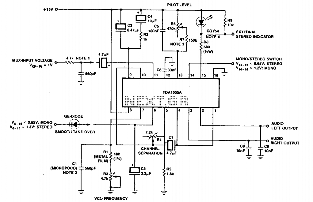
The circuit depicted includes an RC filter (Figure T). The micropico capacitor has a temperature coefficient of 125 x 10^-6 at 60 x 10^-6°C. In simplified circuits, a fixed resistor, such as 620kΩ, can be utilized to ensure a...
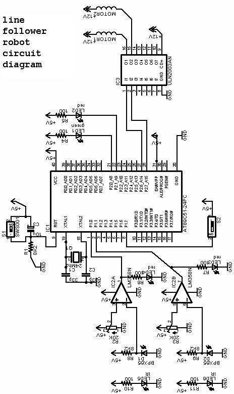
The project involves a line follower robot utilizing the 8051 microcontroller, accompanied by a circuit diagram. A full project report on the line follower or chaser robot is available for download. The line follower robot is designed to autonomously navigate...
At some stage, we will all find ourselves pushing hi-fi equipment just a little too hard, and if lucky, will just find that the sound has become "dirty". If this happens too often or is too severe, tweeters are...
Several years ago, National Semiconductor developed high-performance, user-friendly audio power amplifier circuits known as the LM3886. An additional amplifier was required to bi-amp homemade electrostatic speakers, prompting the selection of the LM3886 chip due to its ease of use,...
Warning: include(partials/cookie-banner.php): Failed to open stream: Permission denied in /var/www/html/nextgr/view-circuit.php on line 713
Warning: include(): Failed opening 'partials/cookie-banner.php' for inclusion (include_path='.:/usr/share/php') in /var/www/html/nextgr/view-circuit.php on line 713