
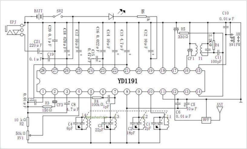
NE5532 IC For FM Stereo Radio Decoder
The NE5532 is a high-performance dual operational amplifier widely used in audio applications, including FM stereo radio decoders. The circuit typically employs the NE5532 for its low noise and high gain characteristics, making it suitable for processing the audio signals received from an FM tuner.
In the circuit design, the NE5532 is configured in a differential amplifier setup to extract the stereo audio signals from the demodulated FM waveform. The input stage of the circuit connects to the output of the FM demodulator, where the audio signals are present. The operational amplifier amplifies these signals while minimizing noise and distortion, which is crucial for maintaining audio fidelity.
Additional components in the circuit may include resistors and capacitors that set the gain of the amplifiers and filter out unwanted frequencies, ensuring that only the desired audio signals are processed. Power supply decoupling capacitors are also typically included to stabilize the power supply voltage and further reduce noise.
The output of the NE5532 feeds into a low-pass filter stage, which smooths out the audio signal, removing any high-frequency components that may remain after amplification. This filtered output can then be sent to an audio output stage, such as a speaker or headphone driver, allowing for the playback of the FM stereo audio.
Overall, the NE5532-based FM stereo radio decoder circuit is an efficient and straightforward solution for audio signal processing in radio applications, leveraging the capabilities of the NE5532 to deliver clear and high-quality sound.This circuit shows about NE5532 IC For FM Stereo Radio Decoder Circuit Diagram. Features: simple circuit, using NE5532 IC. Component: IC, .. 🔗 External reference
Related Circuits
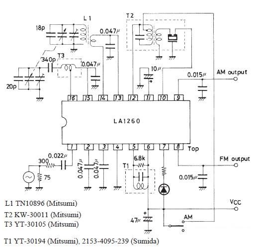
A very simple FM IF MW radio receiver circuit can be designed using the LA1260 IC manufactured by Sanyo Semiconductor. This FM IF MW radio receiver circuit schematic shows that the LA1260 IC can be utilized in AM and...
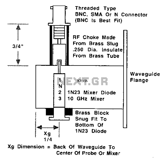
This is a 10 GHz frequency amateur radio waveguide detector. The 10 GHz amateur radio waveguide detector is designed to operate within the microwave frequency range, specifically targeting the 10 GHz band commonly used in various amateur radio applications. The...
This crystal set has been designed to incorporate features from previous radio models. The #62 radio merges the single-piece design of the #48 set with the dual detector functionality of more recent models. It utilizes a dual honeycomb coil...
The YD7312 is a monolithic integrated circuit designed for a dual pre-amplifier circuit with Automatic Level Control (ALC) for the recording and playback amplifier of cassette tape recorders. It is manufactured by Wuxi Youda Electronics Co., Ltd. The YD7312 integrated...
Many antique radios operate on batteries, including tube portables like the Zenith model K-401 and "farm" radios used in rural areas without electrical power. This article provides historical context on battery usage in early radios and offers guidance on...
The schematic diagram illustrates an audio stage utilizing a common-collector circuit. This configuration does not dampen the tuned circuit; rather, it enhances its response, resulting in improved sensitivity and selectivity. Due to the low supply voltage, the subsequent audio...