
Loud ringer for phone using KA2411
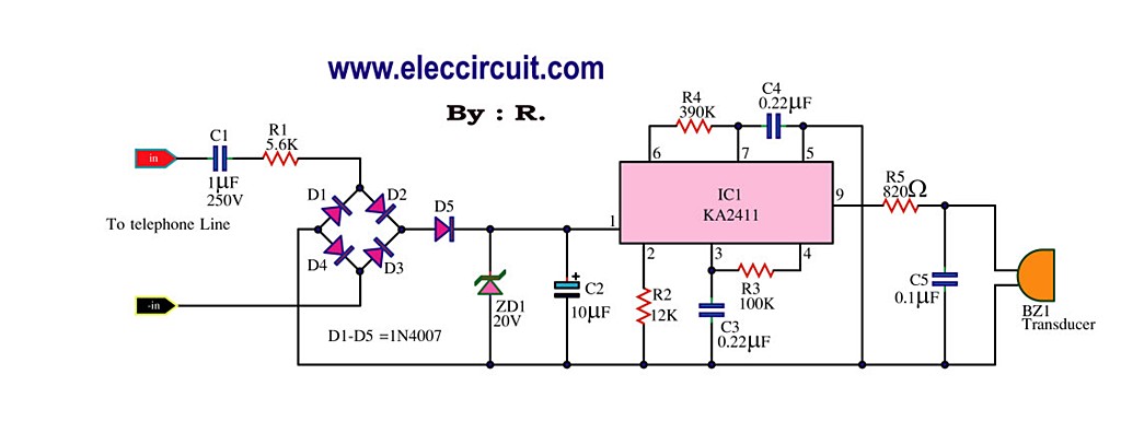
This circuit operates by utilizing a combination of passive and active components to effectively detect and respond to incoming telephone calls. The coupling capacitors, C1 and C2, are essential for isolating the AC ringing signal from the DC bias of the telephone line, ensuring that only the AC component is processed. The bridge rectifier formed by diodes D1 to D4 converts the AC signal to a DC voltage suitable for powering the IC.
The IC (KA2411 or CS8205) is specifically designed for generating ringing signals, making it an ideal choice for this application. Upon receiving the 20V supply, the IC activates its internal oscillator, which produces a square wave output at the desired frequency. This output is then fed through a resistor (R5) to the piezoelectric transducer (BZ1), which converts the electrical signal back into audible sound.
The flashing LEDs serve a dual purpose: they provide a visual indication of the incoming call and synchronize their flashing with the ringing frequency, enhancing the circuit's functionality. The frequency of the oscillation can be adjusted by changing the values of R3 and C3, allowing for customization of the ringing tone.
Overall, this circuit is a practical solution for anyone needing to replace a missing telephone ringer, combining simplicity, effectiveness, and ease of use in a compact design.This phone is loud ringing tone circuit for generating the electricity bell in the old telephone. This circuit is relatively loud. so can use to replacement the same ringer or the original telephone may be lost. We do not need a new phone. The detect ringing signal tone circuit with light and sound. It is easy to use and good quality, Do not enter the power supply. Which as Detect ringing signal tone circuit Or ring tones on the telephone line, a signal incoming calls. When an incoming call, When an incoming call, The C1, C2, will act as a coupling signal AC Volt to diodes D1, D2.
Signal voltage is reduced down to approximately 10V. By D2 to detect, only a negative signal, One extreme to the other end of the wire loop. The D1 detect a positive signal, and the 4 LED. Flashing light attached to it, with frequency of the ringging tone. Which is about 20 Hz. and piezo speaker, show the audio beep. beep, followed by a tone frequency of the ringing. The called signal from the telephone lines is entered through C1, R1 Come to the bridge diode circuit D1-D4, D5 is the positive voltage at 20V supply to pin 1 of IC1 that KA2411 or CS8205 as the Telephone Bell Replacement IC. When IC1 is given the supply volt as I said, it will generator a ringing signals through the R5, to drive the Piezoelectric transducer BZ1 be a bell tone out to hear.
We hear the sound of the Oscillator 2 series, which differ by the output frequency chops to be a frequency generator circuits. Which consists with R3, C3 is low. 🔗 External reference
Related Circuits

A simple instrumentation amplifier circuit diagram utilizing an operational amplifier (op-amp). The equation for gain, along with design, working principles, and construction details, are also provided. An instrumentation amplifier is a type of differential amplifier that has been designed to...
Using an old moving coil instrument, it is easy to create a simple voltmeter that indicates the status of a telephone line at a glance. The circuit's high input impedance allows it to be permanently connected to the line,...
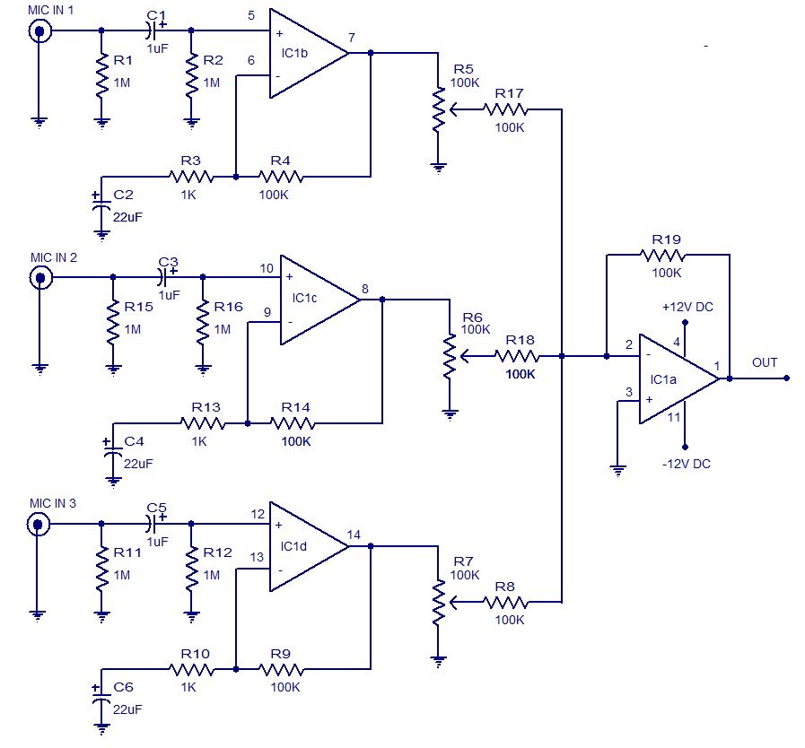
The circuit presented is a three-input microphone mixer and preamplifier utilizing the LM348 integrated circuit. The LM348 is a high-gain, internally compensated quad operational amplifier featuring a class AB output stage. It has a very low input supply current...
Have you ever been using the modem or fax and someone else picks up the phone, breaking the connection? Well, this simple circuit should put an end to that. It signals that the phone is in use by lighting...
Offline telephone tester. This circuit allows for testing a telephone instrument without the need for a telephone line. The design is straightforward. The offline telephone tester circuit is designed to evaluate the functionality of telephone instruments independently of an active...
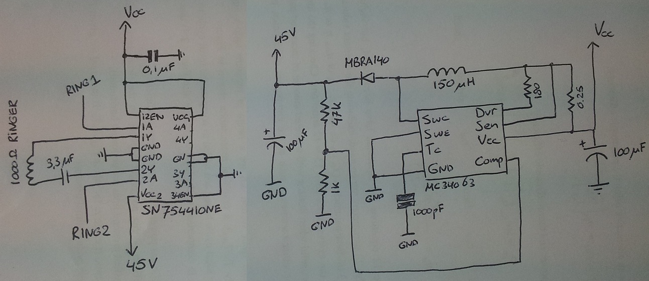
The process involves adapting an old phone for Bluetooth functionality, specifically testing the ringer circuit constructed using schematics from Sparkfun. When connecting a section of the schematic to a 3.5V source (Vcc), an output voltage of 45V is observed,...
Warning: include(partials/cookie-banner.php): Failed to open stream: Permission denied in /var/www/html/nextgr/view-circuit.php on line 713
Warning: include(): Failed opening 'partials/cookie-banner.php' for inclusion (include_path='.:/usr/share/php') in /var/www/html/nextgr/view-circuit.php on line 713