
Dual Precision Monostable Logic circuit (CD4538BC)
The CD4538BC is a dual precision monostable multivibrator, designed to provide a single output pulse of a specified duration in response to a triggering event. Each of the two monostable sections can be triggered independently, allowing for versatile applications in timing circuits. The IC operates over a broad supply voltage range, typically from 3V to 15V, making it suitable for various electronic systems.
The trigger operation is initiated by applying a negative pulse to the trigger input. This pulse causes the output to switch from a low state to a high state for a duration determined by external resistor and capacitor components connected to the timing pins. The pulse width can be adjusted by varying these external components, allowing for a wide range of timing applications.
In retriggerable mode, the CD4538BC can extend the output pulse duration if a new trigger pulse is received before the current output pulse has ended. This feature is particularly useful in applications where the timing interval needs to be adaptable based on external events. The reset operation allows for immediate termination of the output pulse, regardless of the timing components, providing control over the output state.
The IC also includes detailed test circuits for switching and power dissipation, allowing designers to evaluate performance and ensure the circuit operates within specified parameters. The power dissipation test circuit is essential for determining the thermal characteristics of the IC under various operating conditions, ensuring reliability in the final application.
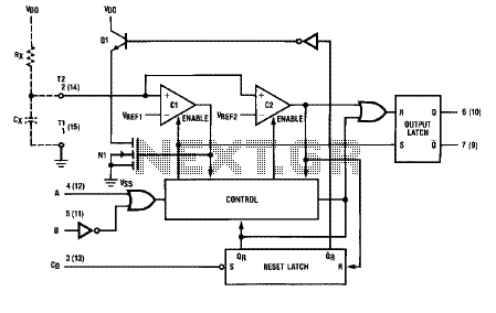
Overall, the CD4538BC offers a robust solution for timing and pulse generation applications, characterized by its precision, flexibility, and efficiency.The logic diagram of the CD4538BC Dual Precision Monostable is shown in the following schematic diagram. This IC such a dual, precision monostable multivibrator with independent trigger and controls, according to the datasheet.
This CD4538BC IC features wide supply voltage range, wide pulse-width range, low standby current, high noise immunity and more. What you will find in the depth of the CD4538BC datasheet are details about Trigger Operation (as seen in the schematic), Retrigger Operation (Retriggerable Monostables Circuitry), Reset Operation, Switching Test Circuit, and Power Dissipation Test Circuit and Waveforms. 🔗 External reference
Related Circuits
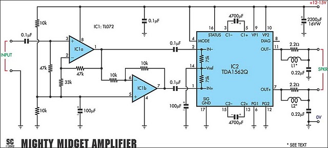
It is based on a Philips class-H audio amplifier IC and can deliver 36W RMS or 70W music power, all from a 13.8V supply. The Mighty Midget Amplifier can provide approximately 36W RMS continuous power into a 4-ohm load...

I constructed this voltage regulator to power my two way mobile radio from the car cigarette lighter circuit. It has many other uses and the voltage can easily be adjusted by the use of a potentiometer. The voltage regulator...
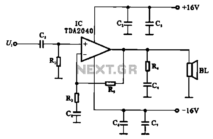
An integrated power amplifier, TDA2040 (IC), can be configured as an OCL (Output Capacitor-Less) power amplifier. The circuit, illustrated in Figure 10-10, operates using a symmetrical ±1V dual supply voltage. The OCL amplifier benefits from the positive and negative...
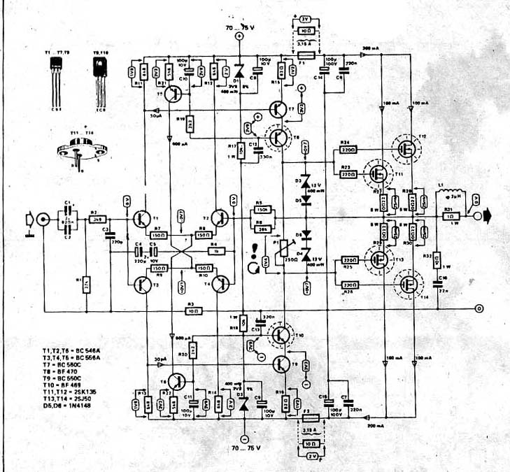
The power amplifier circuit utilizing MOSFET technology has gained significant popularity due to its aggressive sound characteristics when compared to traditional transistors and integrated circuits. It offers both low-frequency and high-frequency responses and is known for its durability. Generally,...
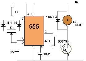
This project utilizes a 555 timer to control the speed of a 6-volt DC motor. Speed adjustment is achieved by rotating a 50 kΩ potentiometer either to the left or right. The circuit employs a 555 timer configured in astable...
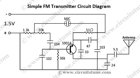
This is a simple FM transmitter circuit schematic diagram that utilizes a single transistor, S9014. The FM transmitter circuit operates by modulating an audio signal onto a carrier frequency, which is typically in the FM band. The S9014 transistor serves...
Warning: include(partials/cookie-banner.php): Failed to open stream: Permission denied in /var/www/html/nextgr/view-circuit.php on line 713
Warning: include(): Failed opening 'partials/cookie-banner.php' for inclusion (include_path='.:/usr/share/php') in /var/www/html/nextgr/view-circuit.php on line 713