
Simple FM Transmitter Circuit Schematic

The FM transmitter circuit operates by modulating an audio signal onto a carrier frequency, which is typically in the FM band. The S9014 transistor serves as the primary amplification and modulation component. In this configuration, the circuit consists of several essential components including a power supply, audio input, the S9014 transistor, a feedback resistor, a tuning capacitor, and an antenna.
The power supply provides the necessary voltage for the operation of the circuit, typically ranging from 9V to 12V. The audio input, which can be connected to various audio sources such as a microphone or audio output from a device, is coupled to the base of the S9014 through a coupling capacitor. This capacitor blocks any DC component from the audio source while allowing the AC audio signal to pass through.
The transistor S9014 is configured in a common emitter arrangement, which provides voltage gain and allows for frequency modulation of the carrier signal. The modulation occurs as the audio signal varies the base current of the transistor, thereby changing the collector current and, consequently, the output signal.
A feedback resistor is connected from the collector to the base of the transistor to provide stability and control the gain of the circuit. The tuning capacitor, in conjunction with an inductor (not specified in the original description, but typically included in FM transmitter circuits), forms a resonant LC circuit that determines the output frequency of the transmitter. This allows the user to tune the transmitter to a specific frequency within the FM band.
Finally, the antenna, which can be a simple wire, is connected to the output of the circuit. It radiates the modulated signal, enabling it to be received by standard FM radio receivers within its range. Proper tuning and adjustment of the circuit components are essential for optimal performance and to ensure compliance with local regulations regarding FM transmission.This is a simple FM transmitter circuit schematic diagram with a single transistor S9014.. 🔗 External reference
Related Circuits

1. A robot may not injure a human being or, through inaction, allow a human being to come to harm. 2. A robot must obey the orders given to it by human beings, except where such orders would conflict...
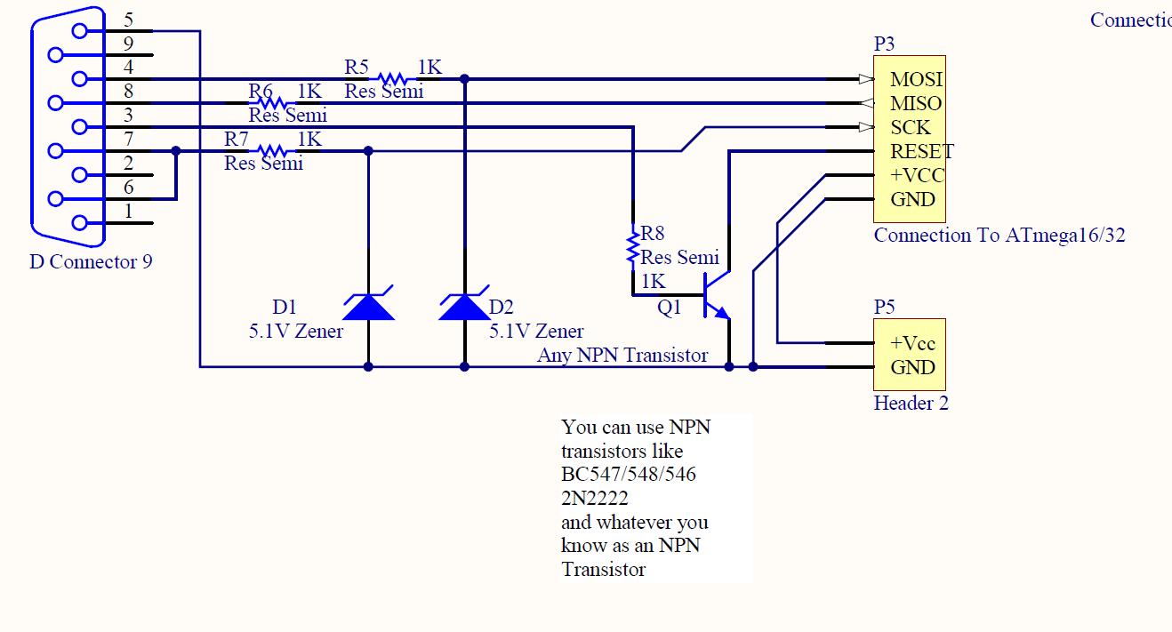
ISP programmer with circuit diagram for AVR Atmega32 microcontroller. This ISP burner circuit is an adaptation of the Pony programmer and uses PonyProg software. The ISP (In-System Programming) programmer designed for the AVR Atmega32 microcontroller facilitates the programming of the...
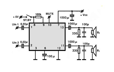
The amplifier circuit utilizing the STK4050 integrated circuit (IC) is known for its robustness and high quality. This article presents a 200-watt power amplifier circuit based on the STK4050. The circuit features an advanced auto wiring diagram with color-coded...
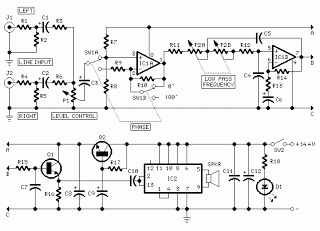
The subwoofer is a speaker designed to reproduce low frequencies, specifically in the range of 20 Hz to 150 Hz. The electronic circuit diagram below illustrates the details of a subwoofer amplifier using the TDA1516, a 22-watt amplifier suitable...
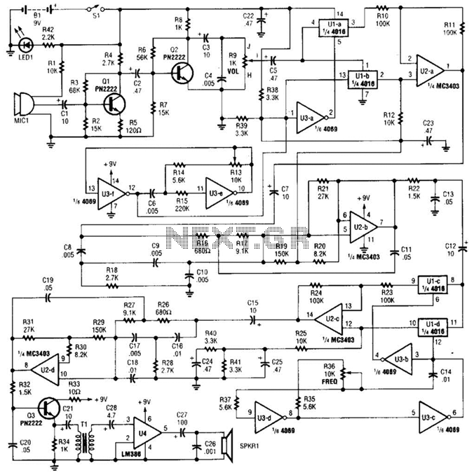
A complete schematic diagram of the voice disguiser is presented. Microphone MIC1 captures the voice signal and transmits it to an audio amplifier, which consists of Q1 and Q2, along with several supporting components. This amplifier features a low-pass...
Most inverters available in the market utilize a modified sine wave to achieve better output at a competitive cost. The modified sine wave unit employs a 50% fixed PWM square wave, with the peaks balanced by a capacitor to...
Warning: include(partials/cookie-banner.php): Failed to open stream: Permission denied in /var/www/html/nextgr/view-circuit.php on line 713
Warning: include(): Failed opening 'partials/cookie-banner.php' for inclusion (include_path='.:/usr/share/php') in /var/www/html/nextgr/view-circuit.php on line 713