
Dual supply for audio amplifiers
The only circuit breaker that should be calculated must withstand the sum of the currents; it will trip if the current exceeds this limit, such as in the event of a short circuit in one of the circuits feeding the three transformers. However, what causes the breaker to trip? Identifying the cause may require various measurements or, alternatively, a keen sense to detect burnt components in the amplifier. The small circuit board, which includes minimal components as shown in the accompanying photo, allows for the connection of two different transformers (or general loads) through two separate circuit breakers. Because this simple circuit does not incorporate a ground connection, it should only be installed within grounded devices and not as an external circuit.
In high-end amplifier designs, the use of multiple transformers enhances audio fidelity by isolating different frequency ranges or channels, thus reducing interference and cross-talk between them. Each transformer serves a specific purpose, with dedicated circuitry that optimizes performance for its assigned channel. The circuit protection mechanism is crucial, as it safeguards the components from overcurrent conditions that may arise during operation.
When designing the power supply section, it is vital to ensure that the transformers are rated appropriately for the expected load. The selection of circuit breakers should also be based on the maximum current draw of the transformers, taking into account any potential inrush currents that could occur during startup. Additionally, the layout of the circuit board must facilitate proper heat dissipation, as transformers can generate significant heat during operation.
In terms of grounding, the absence of a ground connection in this design necessitates careful consideration. It is essential to ensure that all components are housed within a grounded enclosure to prevent electrical shock hazards and to maintain overall system stability. The use of separate circuit breakers for each transformer not only enhances safety but also allows for easier troubleshooting in the event of a failure.
Overall, this configuration exemplifies the complexity and attention to detail required in high-end amplifier designs, where achieving optimal sound quality is paramount, and every component plays a critical role in the overall performance of the system.Most amps acoustic frequencies that make our readers, instead of a transformer power, sometimes required two or sometimes three. This tactic is more common in amplifiers 'High-End', where the altar of high fidelity are all eager to sacrifice their economies.
In these cases the primary, all connected to the network of 220V, paralleled each other yet, through a single security, the nearest outlet. The problem that arises in such a connection is related with as such security. If the amplifier has two transformers, then the defendant one of them leads by one channel (or more generally a set of circuits), and if available, and a third, he'll have as sole purpose supplying circuit protection and control of others.
The only security that should be calculated to withstand the sum of the currents, will burn when it comes current exceeds said limit example where short circuit in one of the circuits that feed the three transformers. But what above all is what caused the 'burnt' it? To find it we should do quite a few measurements or if you have a good nose to smell the components of our amplifier.
The small plaque with the few materials that appear in the photo, allowing the voltage network must be two different transformers (or general cargo) through two separate insurance. Because this simple circuit does not provide for the presence of land, you should place only within grounded devices rather than as an external circuit.
🔗 External reference
Related Circuits
This achievement demonstrates the feasibility of creating a balanced dynamic microphone preamplifier, which is relatively straightforward. This preamplifier is particularly well-suited for microphones with an output impedance ranging from 200 ohms to 600 ohms. The advantages of this preamplifier...
Since I have provided the schematic for John L Linsley-Hood's Class-A amplifier, I felt that some readers may wish to experiment with the concept. Unfortunately, a very low ripple power supply is needed for all Class-A amps, and the...

Another method of using opamps to regulate a power supply is shown below. The power transformer requires an additional winding to supply the op-amps with a bipolar voltage (+/- 8 volts), and the negative voltage is also used to...
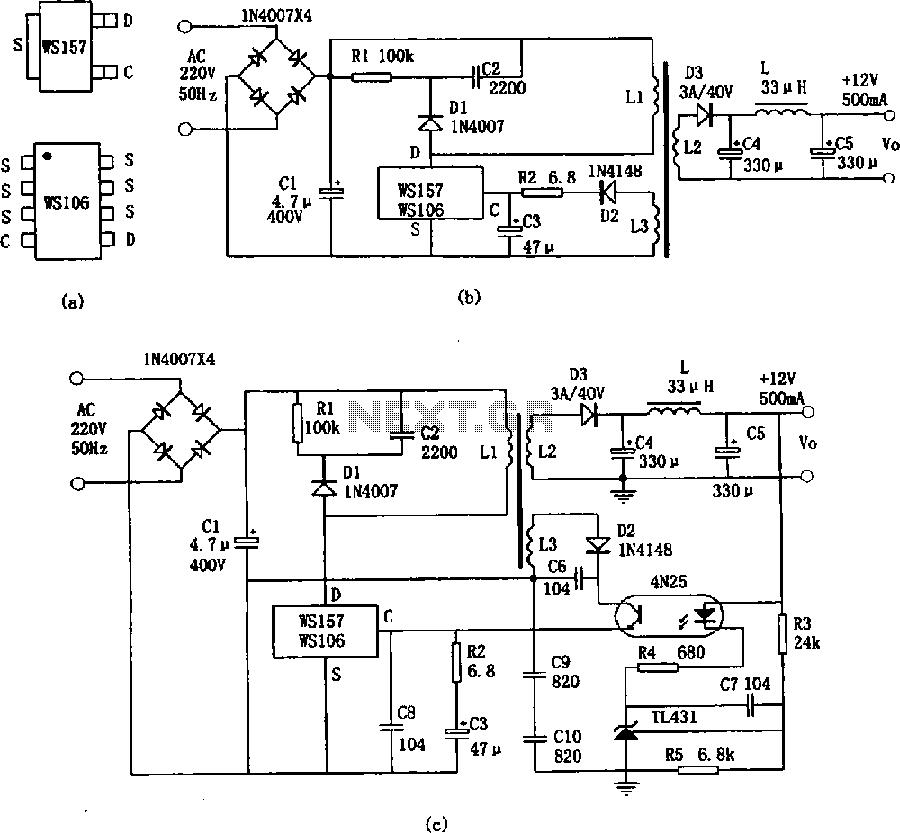
The WS157 or WS106 is a low-power miniature switching power supply that has been developed in recent years. It functions as a regulated switching power supply control device, featuring integrated internal control circuitry and power switches on a single...
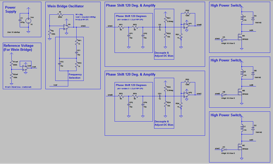
The supply generates a low voltage (less than 18 Volts) low current three-phase sinusoidal waveform. This waveform is utilized to switch high-power MOSFETs on and off, producing a three-phase high current square wave output. It is acknowledged that driving...
This simple and slightly odd circuit can clearly show the level of the supply voltage (in a larger device): as long as the indicator has good 12 volts at its input, LED1 gives steady, uninterrupted (for the naked eye)...