
DUAL TESLA COIL
The dual Tesla coil operates on the principles of resonance and electromagnetic induction, utilizing a unique configuration that allows for efficient energy transfer between the primary and secondary circuits. The primary circuit's inductance and the tank capacitor's capacitance work together to create oscillations at a specific resonant frequency, which is determined by the values of the components used. The spark gap acts as a switch, allowing current to flow through the primary winding when the voltage exceeds a certain threshold, thus generating a magnetic field. This magnetic field induces a high voltage in the secondary coil, resulting in the production of electrical discharges at the top terminal.
The design of the dual Tesla coil emphasizes safety and accessibility, as it is intended for educational demonstrations rather than high-power applications. The use of scrap materials not only reduces costs but also promotes sustainability within the electronics community. The compact size of the coil allows for easy transport and setup, making it suitable for various demonstration scenarios, including science fairs and educational workshops. The effective operation of the "wireless" light bulb trick further illustrates the principles of wireless power transmission, showcasing the coil's ability to transmit energy through the air without direct electrical connections. Overall, this dual Tesla coil serves as an excellent educational tool, providing insights into the fascinating world of high-voltage electricity and electromagnetic phenomena.This area shows the construction and testing of a new half-wave (dual) Tesla coil. This type of coil has two secondaries driven by a single tank circuit. The design shown here is a small and rather in-efficient dual coil constructed from scrap parts for basic purposes. This area shows the functioning Tesla coil being tested as well as some other m inor improvements being made. The tesla coil project is aimed mainly at the scientific and Tesla coiler community. I intend to use my Tesla coil for lightning demonstrations and entertainment. This section shows another different type of Tesla coil design called a half-wave or "twin" Tesla coil. Basically this type is two primaries and secondaries with the primaries wound 180 degrees out of phase in a series fashion.
A single tank circuit capacitor and spark gap drives both opposing primaries and a split phase output develops on each secondary top terminal with the RF ground acting as a "center tap". My dual coil was made entirely from scrap material that was left over after building the main single Tesla coil.
Instead of throwing it away, I decided to build a small table-top dual Tesla coil. The self-contained system is built in a wood and plexiglass box about 6 inches high, 6 inches wide, and about 16 inches long. The HV power is provided by the same small 10 kV, 23 mA oil burner transformer used in earlier experiments.
It was unpotted from its tar case, placed in its own compartment, and sealed in wax (from old candles melted down) becoming and integral part of the coil base unit. The tank circuit is two 30 kV, 0. 0025 uF doorknob type capacitors in parallel (0. 005 uF total). A MMC of 32 10 kV rated capacitors (0. 008 uF total) sealed in wax did not work too well so the doorknobs were used. The series spark gap is a linear static gap (RQ type) quenched with a 12 VDC fan. The spark gap has 4 stainless steel 3/4 inch by 3 inch electrodes giving 3 gaps. The spark gap is series connected through the opposing solenoid-type primary windings of about 10 turns of 1/4 inch copper tubing.
The primary supports are made with small plastic boxes and plastic wire-ties and also reduce the risk accidental contacts with the primary coils. The secondary forms are about 500 turns of close-wound #22 magnet wire on a 1 inch by 12 inch thin clear polycarbonate tube.
PVC connectors are at each end of the secondaries, with the top terminal at one end and RF ground connections at the other. The shared RF ground is connected to a screw that sticks out of the top of the dual Tesla coil base. A screw terminal is also at the top terminal of each secondary coil. Urethane varnish was used to seal the secondaries. Notes - This dual Tesla coil was NOT designed for maximum spark length. The approach was to build such a device from scrap meterials that otherwise would have been thrown away!
This table-top low power unit only produces a spark length of about three inches without any top loads on each secondary. It is mainly used for demonstration of the Tesla coil concept in a less-dangerous package. The system also resonates in the mHZ range, and considerable RF energy is produced by the unit when operating.
The "wireless" light bulb trick works very well with this coil design despite the small sparks. The diagram above is the schematic for my dual Tesla coil design. The dual coil is a half-lambda, or "twin" Tesla coil constructed from spare parts left over from the original Tesla coil trials. AC power is 120 Volts and enters via a main switch and 750 Watt dimmer switch. The dimmer output is fed to an oil burner ignition transformer which produces 10, 000 volts at 23 mA.
The main switch supplys the dimmer and also powers the spark gap quench fan. The quench fan is a 12 VDC fan with its own small DC power supply connected to the main switch before the dimmer. Parallel-connected to the output of the OBIT is a 0. 005 uF tank capacitor (two 2500 pf doorkno 🔗 External reference
Related Circuits

Here is a design for a DC motor speed control featuring: Efficient PWM H-bridge MOSFET architecture. Supply (battery) voltage range from 4.2 to 13 volts. High current capacity for driving large motors (65 amps max). Input compatible with standard...
These circuits allow an ON-ON type DPDT toggle switch to control a twin coil switch machine motor. The handle of the switch can then be used to indicate the route selected. The circuits are also able to control LEDs...
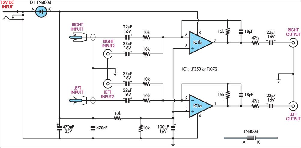
This circuit combines two separate line-level stereo (L & R) signals into one stereo (L & R) output, eliminating the need to switch between two pairs of input signals. It is utilized in a scenario where the stereo audio...
This webpage is designed to provide assistance and information for individuals interested in constructing a Tesla coil. It is recommended to utilize the additional resources available on this page. The electrical line voltage standard in the United States is...
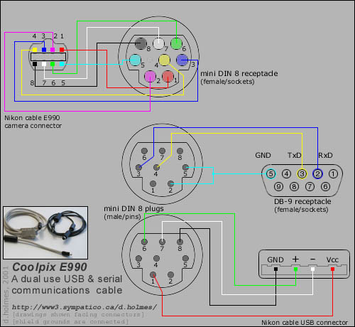
Instructions for creating a combined dual serial and USB cable for the Nikon Coolpix 990 (e990) camera. To construct a combined dual serial and USB cable for the Nikon Coolpix 990 (e990) camera, it is essential to understand the pinout...
The NE568A (NE568AD, NE568AN, SA568AD, SA568AN) is a monolithic phase-locked loop (PLL) that operates from 1Hz to frequencies exceeding 150MHz. It features an extended supply voltage range and a lower temperature coefficient of the VCO center frequency compared to...