
Dual Input-Combining Stereo Line Amplifier
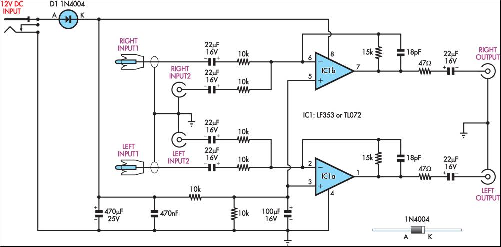
This circuit employs a combining amplifier to facilitate the merging of audio signals from two distinct sources, specifically designed for scenarios where manual switching of audio inputs is impractical. The design incorporates two stereo inputs: one from the TV's audio output and the other from the DVD player's audio output, ensuring seamless integration without audio conflicts.
The combining amplifier is configured to maintain a consistent voltage gain of 1.5, allowing for a slight amplification of the audio signals while preserving the integrity of the original sound. The gain can be adjusted by replacing the two 15 kΩ resistors with resistors of different values, providing flexibility in audio output levels based on user requirements or the specific characteristics of the connected audio devices.
The input impedance of the circuit is set at 10 kΩ, which is compatible with standard line-level audio outputs, ensuring minimal loading on the audio sources. To prevent potential issues with cable capacitance or amplifier input capacitance affecting the audio quality, 47 Ω series resistors are incorporated at the output stage. This isolation helps to maintain signal integrity and reduce the risk of distortion.
Powering the circuit is straightforward, as it utilizes a regulated 12V DC power supply. This design choice ensures stable operation and minimizes the risk of noise and interference from the power source, which is crucial in maintaining high-quality audio performance.
Overall, this circuit represents an effective solution for combining audio signals from multiple sources, providing convenience and enhanced audio reproduction capabilities in home entertainment setups.This circuit takes two separate line-level stereo (L & R) signals and combines them into one stereo (L & R) output, thus avoiding the need to switch between two pairs of input signals. In the author`s application, it is used to feed the stereo audio from a TV receiver and a DVD player into an external amplifier.
The need for the circuit arose beca use of a design peculiarity in the TV receiver. The TV has four A/V inputs and one A/V output. AV1-AV3 accept composite or S-video plus stereo audio inputs and these feed into the TV`s A/V output. AV4 accepts Component video (Y/Pb/Pr) plus stereo audio but unlike AV1-AV3, its audio (and video) signals are not fed to the TV A/V output.
The Y/Pb/Pr input was chosen for use with the DVD player because of its superior video quality, while the audio was to be fed to an external amplifier for improved reproduction. However, manual switching was inconvenient, hence the genesis of this design. In use, the DVD player audio is fed in parallel to TV AV4 and to one input pair of the combining amplifier, while the TV audio output feeds the other input pair.
The amplifier output goes to the external audio amplifier. There is no conflict between the two audio inputs because when AV4 (DVD player) is selected, there is no TV audio output. In all other modes, the DVD player is off. As shown, the circuit has a voltage gain of 1. 5 times (3. 5dB) but this can be altered as required by changing the two 15kW resistors. Input impedance is 10kW and the outputs are isolated from cable and amplifier input capacitance with 47W series resistors.
The circuit can be powered from a regulated 12V DC plugpack. 🔗 External reference
Related Circuits
This application note outlines the implementation of a PSoC (Programmable System-on-Chip) device for controlling a Brushless DC (BLDC) windscreen wiper motor in automotive applications. The design incorporates LIN Bus 2.0 to facilitate the control of wiper operations. The document...
This is an amplified telephone line tap designed to be minimally invasive. The connection to the phone line features a high input impedance and is electrically isolated from the main circuit components. It is intended for use with a...
The circuit presented here can be used for connecting two telephones in parallel and also as a 2-line intercom. Usually, a single telephone is connected to a telephone line. If another telephone is required at some distance, a parallel...
The application circuit operates as depicted below. It typically utilizes a shared TV antenna amplifier and an isolated power switch for the user. There are instances when the TV may not function, yet the antenna amplifier remains powered, leading...
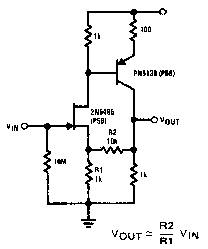
This compound series-feedback circuit provides high input impedance and stable wide-band gain for general-purpose video amplifier applications. The compound series-feedback circuit is designed to achieve high input impedance, which is essential for minimizing loading effects on the preceding stage of...

A repertory dialer phone contains a library of phone numbers that can be entered and dialed, allowing access to up to fifteen frequently used numbers. It also includes the capability to store the last dialed number or an additional...
Warning: include(partials/cookie-banner.php): Failed to open stream: Permission denied in /var/www/html/nextgr/view-circuit.php on line 713
Warning: include(): Failed opening 'partials/cookie-banner.php' for inclusion (include_path='.:/usr/share/php') in /var/www/html/nextgr/view-circuit.php on line 713