
Dual tone decoding
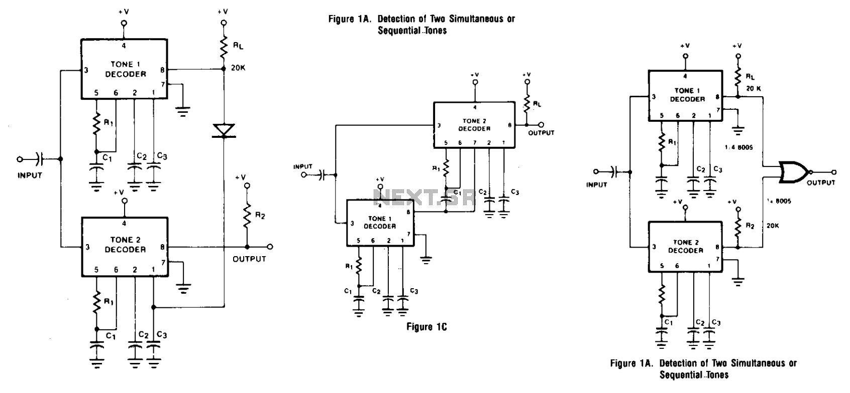
The XR-567 tone decoder circuit is designed for flexibility in decoding tones, allowing for both simultaneous and sequential tone detection. The operation hinges on the proper selection of passive components, specifically resistors and capacitors, which influence the timing and response characteristics of each unit. The interconnected configuration of the two XR-567 units ensures that both must be operational to generate a valid output signal.
The use of a large capacitor (C3) for delaying the turn-off of Unit 1 is critical in applications where sequential tone detection is required. This delay mechanism ensures that Unit 1 remains active long enough for Unit 2 to detect Tone 2, thus preventing premature deactivation that would otherwise inhibit the output signal. The NOR gate's role in the original design is to provide a logic function that only allows output when both tones are detected in the correct order.
In the variation shown in Figure 1B, the removal of the NOR gate simplifies the circuit while still maintaining functionality. The biasing of Unit 2's output stage ensures that it remains inactive until Tone 1 is detected, at which point the circuit becomes responsive to the presence of Tone 2.
The further modification illustrated in Figure 1C introduces a more efficient operational mode by linking the activation of Unit 2 directly to the output of Unit 1. This configuration not only reduces power consumption but also enhances the responsiveness of the circuit to Tone 2, as Unit 2 will only activate if Tone 1 has been detected first.
In applications where transient responses could lead to false outputs, careful consideration must be given to the load characteristics. The load should exhibit a slow response to mitigate the risk of detecting spurious signals from the activation of Unit 1 alone. The XR-267 Dual Tone Decoder offers a compact solution that integrates the functionality of the two XR-567 units, providing a streamlined alternative for tone detection applications.Two integrated tone decoders, XR-567 units, can be connected (as shown in Fig. 1A) to permit decoding of simultaneous or sequential tones. Both units must be on before an output is given. R1C1 and R'IC'l are chosen, respectively, for Tones 1 and 2. If sequential tones (1 followed by 2) are to be decoded, then C3 is made very large to delay turn-off of Unit 1 until Unit 2 has turned on and the NOR gate is activated. Note that the wrong sequence (2 followed by 1) will not provide an output since Unit 2 will turn off before Unit 1 comes on.
Figure IB shows a circuit variation which eliminates the NOR gate. The output is taken from Unit 2, but the Unit 2 output stage is biased off by R2 and CR1 until activated by Tone 1. A further variation is given in Fig. IC. Here, Unit 2 is turned on by the Unit 1 output when Tone 1 appears, reducing the standby power to half. Thus, when Unit 2 is on, Tone 1 is or was present. If Tone 2 is now present, Unit 2 comes on also and an output is given. Since a transient output pulse may appear at Unit 1 turn-on, even if Tone 2 is not present, the load must be slow in response to avoid a false output due to Tone 1 alone.
The XR-267 Dual Tone Decoder can replace two integrated tone decoders in this application. 🔗 External reference
Related Circuits
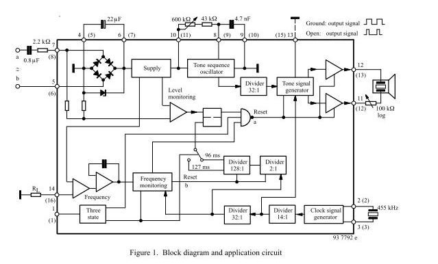
The three-tone ringing integrated circuit U4076B, in conjunction with a piezo transducer or loudspeaker, replaces the normal electromechanical telephone bell. It is operated with the ringing current frequency. The U4076B integrated circuit is designed to generate a three-tone ringing signal,...
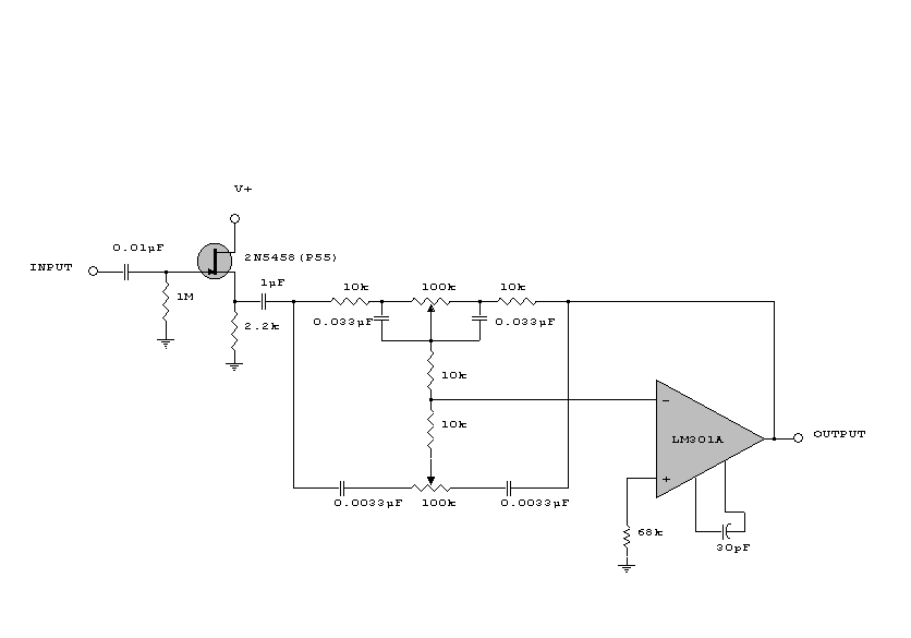
This circuit is a simple series tone control circuit. It utilizes the surgical amplifier LM301A. The JFET 2N3684 provides high input impedance and low noise for the unbuffered operational amplifier, which operates in an equalizer (EQ) configuration. Further details...
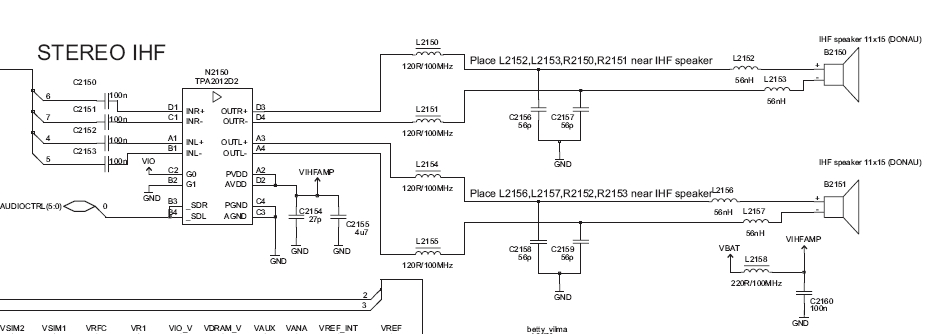
Before proceeding with these steps, ensure that the software calibration and the basic procedures for checking audio circuit components have been completed. The audio circuit schematic diagram is preferred for easy tracking, and this method will aid in future...
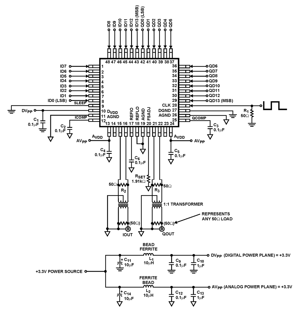
The ISL5929 is a dual 14-bit, 130/210+ MSPS (Mega Samples Per Second), CMOS, high-speed, low-power, digital-to-analog converter (DAC) designed specifically for high-performance communication systems, such as base transceiver stations utilizing 2.5G or 3G cellular protocols. The ISL5929 DAC is engineered...

Voltage regulators have low power dissipation characteristics. The IC 78W series is now very affordable and serves as an economical alternative to simple NPN stabilizers. They provide the advantages of improved regulation, with built-in short-circuit protection up to 1000...
Here is a circuit diagram designed for DIY enthusiasts who aim to construct a dual fan controller utilizing an ATtiny45 microcontroller. The circuit activates the first fan when the temperature reaches a user-adjustable dial setting and engages a second...