
Nokia 5800 Ringtone Buzzer Audio IHF Speaker Repair

1. Identify which channel or speaker is not producing sound. The left channel is marked in pink, and the right channel in red. If both channels have no sound output, the issue may reside in the audio codec chip or the audio amplifier chip. However, further investigation is necessary to determine the exact cause. Begin by examining the outer layers of the entire circuit.
2. Inspect the output filter coils, which are typically small and fragile, designed to protect the speakers. Replace any that are found to be damaged.
3. If all previous checks have been completed and all components are stable, the audio codec chip or the audio amplifier chip may be the source of the problem. However, before proceeding, verify that there is a proper voltage supply to the chip and that it is correctly grounded. This step is crucial, as chips will not function without an adequate power supply.
4. Finally, when addressing the audio codec chip, exercise caution, as this circuit is integrated with the power management circuit, referred to as the power IC.
The Nokia 5800 XpressMusic audio circuit operates through a sophisticated integration of components that ensures sound amplification and control. The audio codec IC is pivotal in processing audio signals, converting digital audio data into analog signals suitable for output through the speakers. The audio amplifier chip enhances these signals, providing the necessary power to drive the speakers effectively.
In the schematic, the audio codec is typically positioned near the microcontroller, facilitating efficient communication. The signal flow begins at the audio codec, where digital audio is received and processed. The processed analog signal is then sent to the audio amplifier, which boosts the signal strength. Each channel's output is routed to the respective speaker, with careful attention to impedance matching to prevent distortion and ensure optimal sound quality.
The inclusion of output filter coils serves to eliminate unwanted high-frequency noise, protecting the speakers from potential damage. These coils are critical in maintaining audio fidelity and should be inspected for integrity during troubleshooting.
Additionally, the power management circuit integrated with the audio codec chip ensures that the audio processing components receive stable voltage levels, critical for reliable operation. Voltage testing at various points in the circuit can help identify potential failures in power delivery, which may affect audio performance.
Overall, a thorough understanding of the schematic and careful examination of each component are essential for effective troubleshooting and repair of the Nokia 5800 XpressMusic audio circuit.before proceeding to this steps make sure that you already done software calibration and the basic steps on how to check audio circuit components which I already explained here: I also preferred the audio circuit schematic diagram, for easy tracking, by which you will also learn in this manner of procedure in the future of your repair career. Now, the Nokia 5800 xpressmusic schematic diagram shown below an audio circuit which is feed from a the audio codec IC (not shown on the picture) Unlike most Nokia Audio circuits in some models, the 5800 xpressmusic has an audio amplifier chips or IC that amplifies the audio signal before it goes through the IHF ( Intermediate High Frequency) Speaker. This chip also designed to controls the audio signal`s volume. It has two channels, the left and right channel, which is so-called stereo type amplifier. The components layout and connection path lines with each certain components from the schematic diagram is in the picture below.
The chips layout which I in-lined with colors indicates each certain components that are being shown or listed from the schematic diagram in the above image. Assuming that we already restore or flash it with its original or desired flash firmware and been already test the speaker working fine, but the problem still exist, 1.
Determine which channel or speaker got no sound output. the left channel is where I colored "pink" and the right channel is colored "red". if both channel speaker got no sounds output, preferably the problem lies from the audio codec chip or from the audio amplifier chip, but don`t rush on there that quickly, it`s unsure yet and ain`t that easy to determine which one causes the problem. Always start from outer layer of the whole circuit, 2. Check the following output filter coils, the value of this said coils are too small enough and quite possible easy to break and typically designed for the speakers protection.
Replace if found busted. 5. In this stage considering that all of the above is already done and those components were all fine and stable. this where we suspect the audio codec chip or the audio amplifier chip causes the problem. BUT BEFORE THAT, in working on Integrated Circuit or chip, always check first if there is a voltage supply on it and or properly connected to ground lines.
In this manner you are checking and testing the chip`s itself, ob-course chips won`t work without a proper power supply on it. 8. The last stage is working on the Audio codec chip, in this stage needs extra care for an audio codec circuit is also combined with power management circuit.
This what called the power IC. 🔗 External reference
Related Circuits
These accessories are low-cost, high-speed, bifet-input operational amplifiers utilizing internally compensated voltage (BI-FET II technology). They require low supply voltages while offering a wide gain bandwidth product and fast slew rate. Additionally, well-matched high voltage JFET input devices accommodate...
Building ESLs involves the use of tools and materials that if handled improperly can be hazardous. Please make sure you know how to use these things before you begin. By all means, use safety glasses at all times. If...
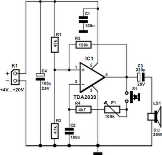
A powerful buzzer in the room, combined with a pushbutton at the bottom of the stairs or in the kitchen, could be very useful in such situations. The core of this circuit is formed by IC1, a TDA2030. This...
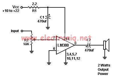
A simple audio amplifier can be designed using the LM380 along with a few external components. This amplifier features a wide supply voltage range, an input impedance of 150 kΩ, low distortion, and a current capability of 1.3 A. The...
The schematic diagram presented is of a twin "T" phase shift oscillator, an audio oscillator. This oscillator derives its name from the phase shift network formed by resistors R3, R4, and capacitors C1, C2, and C3. This network shifts...

Creating a variable space in a small room can be enjoyable; however, designing an actuator to move a wall or room partition poses challenges. This can be achieved using an analog audio line delay. To implement a system that allows...