
DUM23-48 / 300 DC power distribution unit electrical schematic diagram

The electronic schematic involves several critical components that facilitate the operation and safety of the system. The Hall current sensors, represented by B2 and B3, are essential for measuring the current flowing through the circuit without direct electrical contact. These sensors provide real-time feedback on current levels, which is crucial for monitoring and controlling the system's performance.
Fuses FU9 and FU10 are integrated into the circuit to protect against overcurrent conditions. These components act as safety devices that interrupt the electrical flow when excessive current is detected, thereby preventing potential damage to the circuit and connected devices.
The AP646 alarm signal is an important feature linked to the fuse board. This alarm system is designed to alert users of any issues related to the fuses, such as a blown fuse condition. By providing immediate feedback, it enhances the system's reliability and user safety.
The user interface panel, comprised of terminals X24, X26, and X29, allows users to interact with the system easily. This panel may include indicators, buttons, or displays, enabling users to monitor system status and make necessary adjustments.
Finally, the XT terminal is designated for the outlet connection, ensuring that the system can interface with external power sources or devices as required. This outlet serves as a critical point for powering additional equipment or providing power to the overall system.
Overall, the arrangement and functionality of these components are vital for the effective operation and safety of the electronic system. Each element plays a specific role, contributing to the overall performance and user experience.As shown, B2 (13), B3 (14) for the Hall current sensor; FU9 (9), FU10 (10) for the fuse; AP646 alarm signal for the fuse board; terminal X24, X26 and X29 is a user interface panel; XT for the outlet.
Related Circuits
The Up Alarm is designed to provide an audible alert when sunlight is detected or when a light source is activated in a dark environment. It can also be utilized to sense various light sources such as beams or...
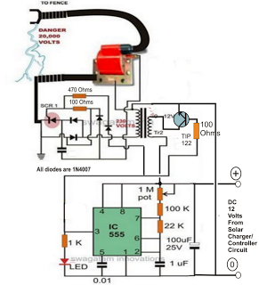
A fence charger or energizer is a device used to electrify a fence or boundary to protect the premises from human or animal intrusions. These boundaries are often located in large fields and parks, typically away from urban areas,...
The Inter-Power SWR-5 upper right isn't worth a penny. Got it from a mate to use with a beacon, but I burnt it out with only 3.5-4W morse signal on 70cm. Removed the bridge and installed my own pick-up...
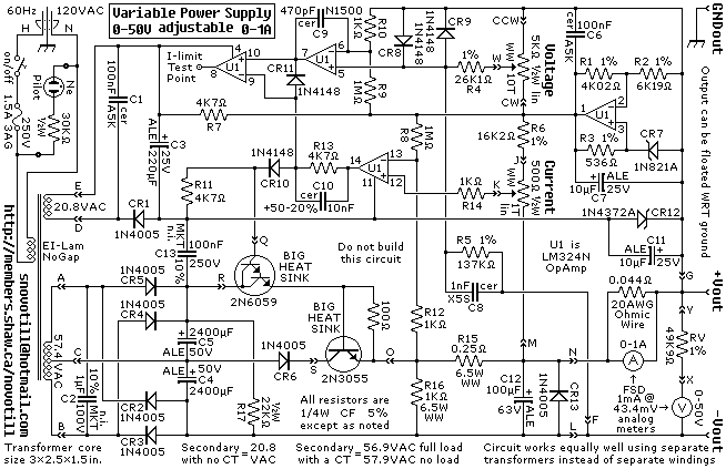
A reverse-engineered circuit diagram of a high-end commercial variable laboratory power supply. This unit is constructed using a standard operational amplifier and readily available components. While the design employs a single transformer with dual output windings, it can also...
Today, simplicity and minimal controls are required for the design of a handheld device. It would be very useful if a circuit allows us to turn the power on or off. A handheld device requires an efficient power management circuit...
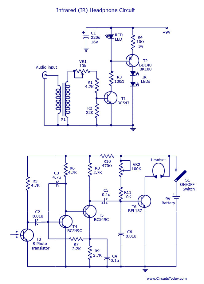
This document outlines a simple infrared (IR) headphone circuit designed for listening to television or radio without disturbing others. The IR headset is a preferable option for beginners compared to FM headsets due to its desirable sound quality that...