
0-50V 1A Laboratory Power Supply Variable Voltage

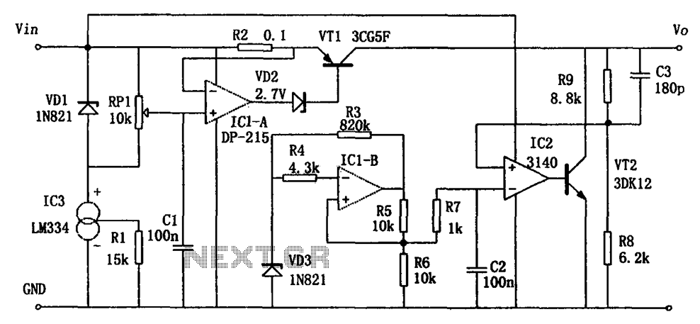
The circuit diagram represents a variable laboratory power supply, which is a crucial tool in various electronic testing and prototyping applications. The primary component of this power supply is an operational amplifier (op-amp), which is utilized for voltage regulation and control. The op-amp receives feedback from the output voltage, allowing it to adjust the output dynamically to maintain a stable voltage level as load conditions change.
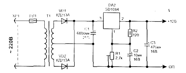
The power supply design incorporates a transformer that steps down the AC mains voltage to a lower AC voltage suitable for the op-amp's operational range. The dual output windings of the transformer provide versatility in output voltage options, allowing users to select the desired voltage level for their specific applications.
The circuit typically includes additional components such as diodes for rectification, capacitors for filtering, and resistors for setting gain and feedback levels. The rectifier converts the AC voltage from the transformer into a pulsating DC voltage, which is then smoothed by the filter capacitors to provide a more stable DC output.
Furthermore, the circuit may include protection features such as fuses or circuit breakers to prevent damage from overload conditions. The design's simplicity and use of common components make it an accessible option for hobbyists and professionals alike, facilitating the construction of a reliable variable power supply without the need for specialized or expensive parts.
Overall, this reverse-engineered circuit diagram serves as a valuable resource for understanding the workings of a variable laboratory power supply, highlighting the effective use of basic electronic components in achieving complex functionality.Reverse engineered circuit diagram of an expensive commercial variable lab power supply. This unit is designed around an ordinary op-amp and easy to obtain parts. Although the unit uses a single transformer with two output windings the circuit works equally well using a big transformer and a little transformer. Disclaimer All files are found using legitimate search engine techniques. This site does not and will not condone hacking into sites to create the links it list. We will and do assume that all links found on the search engines we use are obtained in a legal manner and the webmasters are aware of the links listed on the search engines. If you find a URL that belongs to you, and you did not realize that it was "open to the public", please use the report button to notify the blogmaster of your request to remove it or it will remove within 24 hours.
This is not an invitation for webblog haters to spam with requests to remove content they feel that is objectionable and or unacceptable. Proof of URL ownership is required. NOTICE: This Blog Has Already Been Reviewed And Accepted By Blogger. com 🔗 External reference
Related Circuits
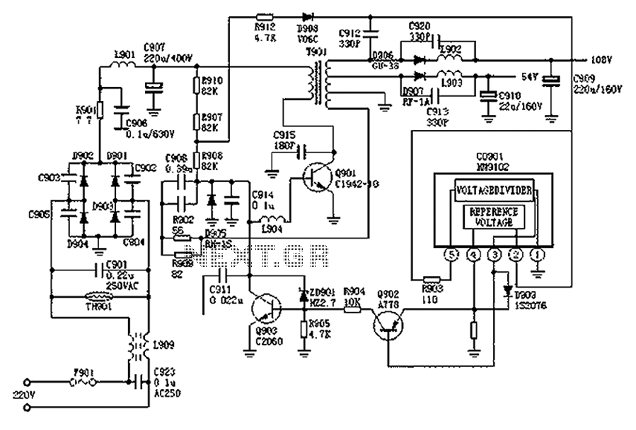
The Hitachi NP8C switching power supply circuit is illustrated in FIG. The Hitachi NP8C power models include CTP236, CEP320D, CRP350D, 450D, Furi HFC-236, 450, and Venus C37-401, C46-1, C563, among others. This circuit was widely used in early Chinese...
A 12V power supply is an essential and useful resource for laboratories, as it is employed by a wide range of electronic circuits and devices. A 12V power supply circuit can be constructed based on specific ampere requirements. A...
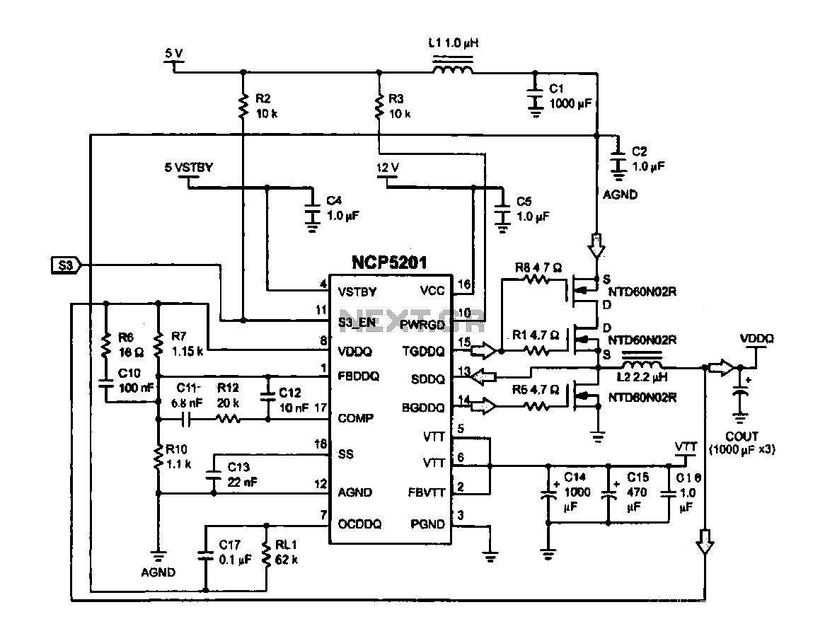
Computer memory power supply circuit (NCP5201). This circuit illustrates a typical power supply configuration for computer memory, utilizing the NCP5201 power management chip. It features a dual-output design. The NCP5201 is a highly integrated power management solution designed specifically for...
The motor vehicle currently represents a no-emission automotive solution, serving as a green means of transportation that is expected to significantly impact human society in the 21st century. The direct-flow brushless electric machine has emerged as a leading technology...
This achievement demonstrates the feasibility of creating a balanced dynamic microphone preamplifier, which is relatively straightforward. This preamplifier is particularly well-suited for microphones with an output impedance ranging from 200 ohms to 600 ohms. The advantages of this preamplifier...
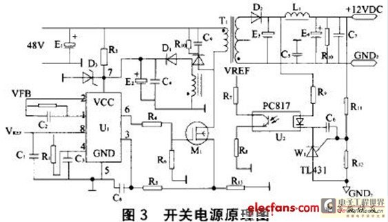
The circuit functions as a switching power supply designed to operate alongside a linear regulated power supply. Key characteristics include high efficiency and low dropout voltage. It effectively filters out high-frequency ripple voltage and manages instantaneous voltage variations, making...