
RF power and VSWR meter
The Inter-Power SWR-5 is a standing wave ratio (SWR) meter designed for use in VHF and UHF applications. This device is used to measure the efficiency of an antenna system by determining the ratio of reflected power to transmitted power. The original design may have limitations, as indicated by the user's experience with burning out the device under low power conditions (3.5-4W) on the 70cm band.
After modifying the SWR-5, the user removed the original bridge and replaced it with a custom pick-up line, which significantly improved the performance for VHF/UHF applications. This modification is indicative of a common practice among amateur radio operators to enhance the functionality of existing equipment. The user also referenced the performance of older SWR meters, such as those from Hansen or Reace, which, despite their age, can provide reliable readings if handled carefully.
The mention of using a Wavetek Model 3001 signal generator for testing antennas illustrates the practical application of the SWR meter in evaluating antenna performance at specific frequencies, such as 180-190 MHz. The choice to use N-connectors for improved durability and professionalism further demonstrates the focus on quality in amateur radio setups.
The discussion of coaxial cables highlights the importance of selecting the right type for optimal performance. RG8/U is preferred over RG213/U due to its looser braid, which can facilitate better connections in certain setups, particularly in older equipment. The user also emphasizes the need for clean and corrosion-free connections to ensure accurate measurements and reliable operation.
Overall, the modifications and techniques described reflect a hands-on approach to enhancing the functionality of RF measurement tools, showcasing both creativity and technical knowledge in the field of amateur radio operation.The Inter-Power SWR-5 - upper right - "isn't worth a penny". Got it from a mate to use with a beacon, but I burnt it out with only 3.5-4W morse signal on 70cm. Removed the bridge and installed my own pick-up line (suggested by LA8OJ) and now it is fb for VHF/UHF. The old Hansen, Reace or whatever make "SWR-meter from 1968 (from J. B. Lowe) or later has a relatively good bridge, it works fb on 2m - provided careful operation, sensitivity is very good on 2m!
It is easy to destroy, but works fb with level down to 10mW, have used it on 180-190MHz to test TV-receiver antennas using Wavetek Model 3001 signal generator, but mounted N-connectors to make it look sufficient professional at work, see next note. The Inter-Power SWR5 was renovated and since the meter and box was so nice looking I decided to keep it and remove the useless bridge. Mounting wire is pulled under the braid for a length of 40mm. It is easier for the old type RG8/U, where the braid often is somewhat looser than for RG213/U. I wouldn't think about using RG214/U! It was some struggle to mount the bridge, and solder in the right order since it is just as must space as you need.
Another application of the same technique. It is so easy to build pick-up bridges, it is just fun. Here is my 2m line - permanently inserted between the PA to antenna. Suppose RG8/U type coax-cable is better than RG213/U since the braid may be somewhat loose, but must not be dark and corroded. 🔗 External reference
Related Circuits
This 1 kHz linear-scale analog frequency meter circuit utilizes the 555 timer as a pulse counter. The frequency is displayed on meter M1, a 1 mA meter, which can be calibrated to indicate readings from 0 to 1 kHz. The...
The intention was to develop a morning exercise machine, but the challenge was the absence of a suitable high-power amplifier. Since the exercise machine operates on battery power, the search for a solution persisted for several months. Eventually, the...

The Kelvin scale version reads from 0 to 1999 K theoretically, and from 223 K to 473 K actually. The 26 kΩ resistor brings the input within the ICL7106 common-mode voltage range; two general-purpose silicon diodes or an LED...
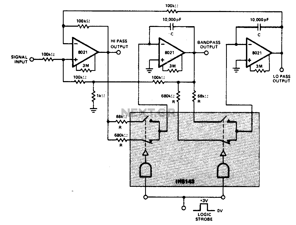
A constant gain, constant Q, variable frequency filter that provides simultaneous low-pass, bandpass, and high-pass outputs. With the specified component values, the center frequency will be 235 Hz and 23 Hz for high and low logic inputs, respectively, with...
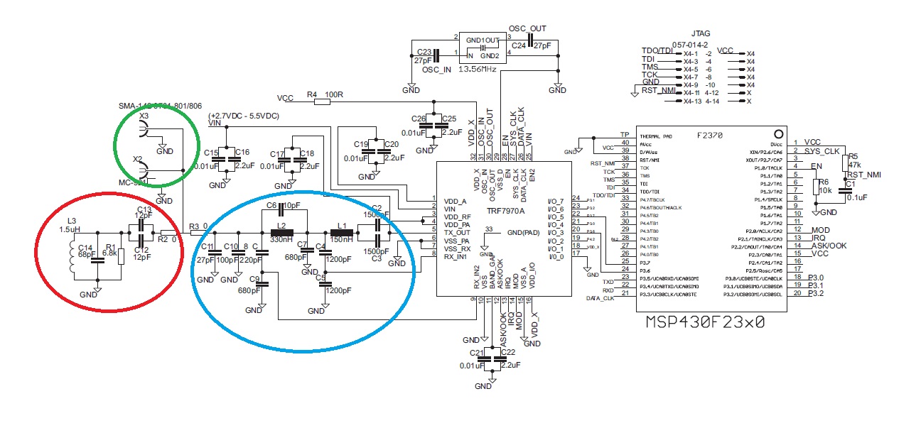
The "green area" is designated for the placement of the TRF7970A's antenna, which should be connected between two 0-ohm resistors. The antenna can be constructed step by step following the guidelines in the document "Antenna Matching for the TRF7960...
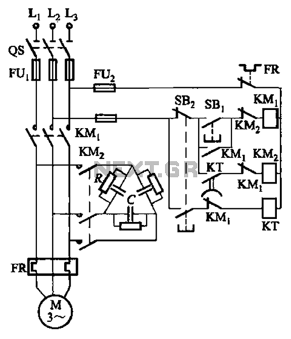
The circuit illustrated in Figure 3-151 consists of capacitor banks arranged in a specific configuration. Figure 3-151 (a) depicts capacitor banks connected in a shaped manner, which is suitable for use with shaped or Y-connected motors. Figure 3-151 (b)...
Warning: include(partials/cookie-banner.php): Failed to open stream: Permission denied in /var/www/html/nextgr/view-circuit.php on line 713
Warning: include(): Failed opening 'partials/cookie-banner.php' for inclusion (include_path='.:/usr/share/php') in /var/www/html/nextgr/view-circuit.php on line 713