
Dynamo Current and Voltage Regulator
The dynamo charging circuit described operates with specific connections and components that ensure efficient voltage regulation and protection against potential failures. The battery connections are indicated as B+ and B-, while D+ and D- connect to the dynamo brushes. The DF terminal connects to the field winding, which is crucial for the operation of the dynamo. It is emphasized that not all dynamos follow the same wiring convention, which is essential for compatibility with the regulator circuit.
The regulator itself is designed to manage voltage and current effectively. The time constant in voltage regulating mode is determined by capacitor C4 and the parallel resistance of resistors R11 and R12, allowing for gradual voltage adjustments. In contrast, during current limiting mode, the high gain of operational amplifier U1D results in a quicker and asymmetrical response. This is particularly important when handling abnormal pulsed loads, ensuring that the average current remains below 20A to protect both the diode D1 and the dynamo.
The inclusion of a fuse (F1) serves as a critical safety feature against potential diode failure. If D1 were to fail and short, the fuse would prevent reverse current that could damage the dynamo. In the event of an open fuse, the circuit adapts by regulating the dynamo voltage rather than the battery voltage, using diode D5 to inject current into the control pin of U1A, thus maintaining voltage levels around 16.5V.
Additional protective measures include diodes D18 and D6, which safeguard the gates of the MOSFETs from high voltage spikes, particularly during improper system startup. The snubber circuit formed by C6 and R23 is designed to mitigate transient events during MOSFET operation, although its necessity may be reduced due to the rapid switching characteristics of diode D8.
The circuit incorporates Schottky diodes at critical points (D1 and D8) to minimize voltage drop and heat generation, enhancing overall efficiency. The precision voltage reference IC (U2) is highlighted as a vital component, as it ensures accurate voltage regulation without the unreliability of potentiometers or standard Zener diodes. This design choice is particularly relevant in environments where reliability is paramount, such as marine applications.
Overall, the circuit is engineered to provide robust performance while safeguarding against typical failures, ensuring a stable and reliable charging solution for dynamo systems.In the typical dynamo charging circuit, B+ and B- are the battery connections. D+ and D- go to the dynamo brushes, while DF is the field connection, with its other end returned to D+ inside the dynamo. Please note that not all dynamos return the field winding to the positive output! My regulator circuit, as shown here, works only with dynamos connected in this way. For further clarity, here`s the internal wiring of a standard dynamo. A dynastarter is just like this but with an additional field winding added, connected from D+ to an additional terminal, which is used to apply battery current for starting.
This regulator operates with a rather slow time constant when in voltage regulating mode. The time constant is given by C4 and the parallel resistance of R11 and R12. When operating in current limiting mode, the high gain of U1D makes the time constant a lot faster, and asymmetrical: The regulator will adjust the output down faster than back up. In the presence of an abnormal pulsed load, this will make the circuit adjust for an average current somewhat lower than 20A, protecting D1 and the dynamo.
Also, if the fuse is open, dynamo voltage limiting will have a fast attack time. The fuse was included mainly as a safety measure against failure of D1. This diode gets pretty warm, and could conceivably fail if it comes loose from the heatsink. If it fails shorted, F1 would avoid the destruction of the dynamo through reverse current. Anyway the risk would be low, because a failure like this would most likely end up with D1 opening rather than shorting, but fuses are cheap, so it's not bad to include one... If F1 is open, the dynamo voltage can no longer be regulated by sensing battery voltage, and also there would be no current to sense.
In order to keep the dynamo voltage from soaring, D5 will inject some current to pin 2 of U1A, and so the circuit will now regulate the dynamo voltage, not battery voltage, to about 16.5V, keeping matters safe until someone replaces the fuse - hopefully before running the battery down! D18 and D6 are there only to protect the MOSFET gates against abnormally high voltage, which could happen when the operator does stupid things such as starting the system without a battery connected.
Otherwise they would not be needed. C6 and R23 form a snubber which eats up any transients that could happen during the MOSFET switching. Most likely this snubber isn't needed, thanks to the high switching speed of D8 combined with the comparatively slow switching of the MOSFET, which is limited by the slew rate of the TL084.
C8 might not be needed when the battery wiring is short and direct, but for safety I suggest to include it in all cases. I added it during the tests of the prototype, after having the system break into self-oscillation at 300kHz due to battery cable inductance resonating with C1!
This event was useful to see how fast Q4 can really switch! It produced quite a clean 300kHz square wave... Needless to say, switching at a nominal 100Hz, its switching losses are essentially nil. Maybe the emitter follower would not be necessary at all, but surely it adds a bit to efficiency of the regulator. The use of Schottky diodes at D1 and D8 was decided because of their low voltage drop. This means less heat (mostly for D1), and heat is the worst enemy of electronics, as you know. Standard diodes could be substituted, but I don't recommend it. U2 is not a Zener diode, but a precision voltage reference IC. To answer a very common question I often get: No, you should not replace it by a standard Zener diode.
Zeners are not precise enough. This circuit avoids the use of potentiometers for voltage setting, because they are unreliable, particularly in a marine environment. It relies on precision components to get the correct voltage, and this won't work with Zeners. If you can't find an LM336Z-5.0, you can use some other 5V reference IC (also called "reference diode", even if it is much more than a diode).
And no, you cannot use a 7805 or any other three-terminal regulator, because they would mess up the correct startup of the dynamo: While Q1 is halfways on, a three terminal regulator would produce a lower voltage on pin 3 than pin 2 of U1A, which would make the circuit switch off Q4 and interfere with proper dynamo startup. 🔗 External reference
Related Circuits
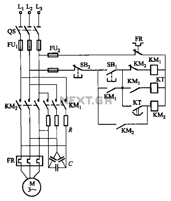
The circuit depicted in Figure 3-35 demonstrates a method for starting a motor that transitions to full voltage through a step-down switching process. This approach provides an uninterruptible power supply, effectively preventing issues related to switching currents that may...
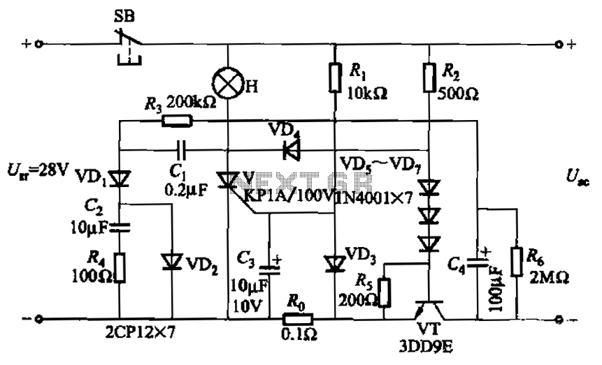
Capacitor C3 is used to determine the cutoff power, specifically the voltage threshold (VT cutoff), which influences the delay time selection. The schematic includes a reset button, SB, that is utilized to reset the system after a failure has...
This LM10 circuit can be used as a low voltage, low current voltage source or reference. This circuit regulates the voltage from the power supply to provide a stable output. The LM10 is a precision voltage reference and regulator integrated...
In a prior post titled "Timing is Everything," the application of PWM (Pulse Width Modulation) signals for controlling devices such as LEDs was discussed. This technique is particularly beneficial when working with digital devices, including microchips and microcontrollers, which...
At this voltage regulator prototype the maximum current, with output shortcircuited it was only 0.5 A, so no overheating occurred. In this DC voltage regulator circuit, T1 is for current limitation. As soon as the voltage on the R2...

A simple 5 Volt regulated power supply unit (PSU) featuring overvoltage protection. This 5 Volt regulated power supply is designed for TTL and 74LS series integrated circuits. The 5 Volt regulated power supply unit is an essential component in electronic...