
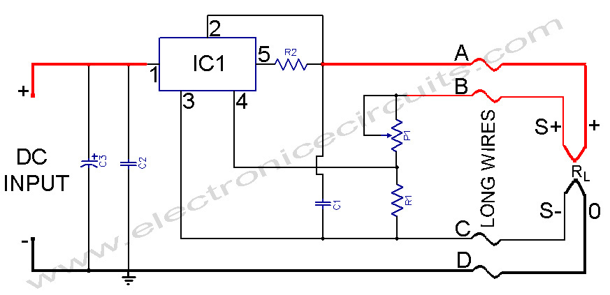
Shortcircuit protected voltage regulator
The described voltage regulator circuit utilizes a combination of a voltage regulator IC, such as those from the LM7805 or LM7812 series, along with additional components to enhance its functionality and provide short-circuit protection. In this configuration, T1 serves as a current limiting transistor, which is crucial for preventing excessive current flow during fault conditions. The operation of T1 is governed by the voltage across resistors R2 and R3; when this voltage exceeds approximately 0.6 to 0.7 volts, T1 activates, cutting off the base current to T2, thereby disabling it and preventing further current flow.
The resistors R3 and R4 are configured as a voltage divider that sets the base voltage for T2, which is essential for regulating the output voltage. If the output experiences a short circuit, the current through R2 and R3 will increase, triggering T1 and protecting the circuit from damage due to overheating. The design effectively manages power dissipation, which is a critical consideration in voltage regulator applications, especially when high currents are involved.
For applications requiring higher output currents, the addition of a complementary transistor, T2, is necessary. This transistor can handle increased load demands, allowing the circuit to provide up to 3 A of output current. The design ensures that even under fault conditions, the circuit remains stable and safe, making it suitable for a variety of applications where reliable voltage regulation is required.At this voltage regulator prototype the maximum current, with output shortcircuited it was only 0,5 A, so no overheating occured. In this dc voltage regulator circuit, T1 is for current limitation. As soon as the voltage on the R2+R3 becomes higher than 0,6-0,7 V, T1 opens, which leads to a reduction to zero of the T2 base current.
The voltage at which the shortcircuit protection starts to act, is given by voltage sum on R2 and R3. R3 and R4 resistances form a T2 voltage divider. Voltage regulator IC’s, with 3 pins, from LM7805 and LM7812 series are excellent for usage in voltage regulator circuits. If you need higher currents, up to 3 A, you must add a complementary transistor, T2 in this schematic.
In a normal design, in case of a shortcircuit, the power dissipation can be very high. This problem can be solved using the voltage regulator design presented bellow. 🔗 External reference
Related Circuits
This circuit is used to convert a mono audio signal into a stereo signal that can be panned between the left and right channel by a 0-10V control signal, it is intended for analog synthesizer systems. The circuit is...

A voltage-controlled oscillator using the NE555. This circuit is commonly referred to as a voltage-to-frequency converter because the output frequency is altered by varying the input voltage. As previously noted, pin 5 serves as the voltage control terminal, which...
As mentioned in the chapter about the DAC, this circuit shifts the voltage output range. The following diagram explains its operation and structure. The circuit's outputs are connected to the input pins of the power operational amplifiers. The described circuit...
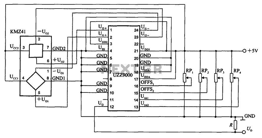
The UZZ9000 KMZ41 detection circuit is configured based on the voltage output type and angle. It operates with a +5V power supply. Potentiometers RP1 and RP2 are used for offset voltage adjustment, while potentiometers RP3 and RP4 are utilized...
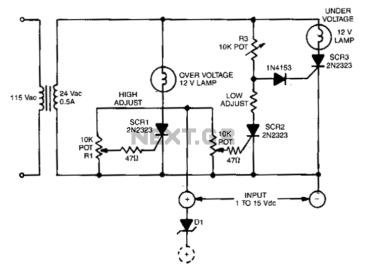
This circuit is capable of monitoring any voltage potential ranging from 1 to 15 V. It features two lamps that indicate any undesirable voltage variations. The voltage differential between the lamp turning on and turning off is approximately 0.2...
L200 Power Supply Regulator. There are applications in which it is important for the supply voltage to be largely independent of the load level. The L200 is a versatile voltage regulator designed to provide a stable output voltage while maintaining...