
DZW75-48/5050II input circuit
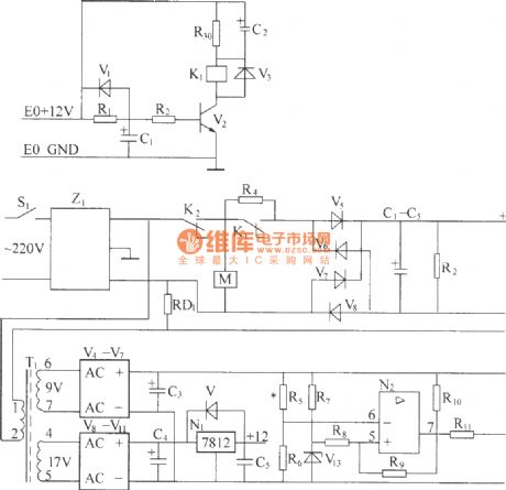
The circuit operates by first filtering the incoming 220V AC voltage through the Z1 circuit filter. This component is crucial for eliminating high-frequency noise and voltage spikes that could damage downstream components, specifically the bridge rectifier. The rectifier converts the filtered AC voltage to a pulsating DC voltage, which is then smoothed out by the capacitor bank to provide a steady 300V DC output. The inclusion of R4 as a current-limiting resistor is essential for protecting the circuit during startup and preventing inrush current that could lead to component failure.
The relay K2 plays a pivotal role in the overvoltage and undervoltage protection mechanism. When the AC voltage is within acceptable limits, K2 remains closed, allowing current to flow to the load. If the voltage exceeds or drops below predefined thresholds, K2 opens, disconnecting the load and preventing damage. The design also incorporates a delay circuit to ensure that transient conditions do not trigger unnecessary relay operation, enhancing the overall reliability of the system.
The Z1 filter's ability to suppress common mode and differential mode noise is particularly important in environments with high electromagnetic interference (EMI), ensuring that the rectifier operates efficiently without being affected by external disturbances. This isolation is critical in applications where sensitive electronics are involved, as it enhances the longevity and stability of the system.
Overall, the described circuit effectively transforms AC voltage to DC while incorporating essential protection and filtering mechanisms, ensuring reliable operation in various electrical conditions.220V (5Hz) alternating voltagepass Z1 circuit filter filtering, then it will send to the connect point of AC over voltage, under voltage protect relay K2. When normal working, K2 connect point should up-close, connect AC 220V voltage to AC current-limiting resistance R4 (after starting up, delay period of time, R1 is short-circuit by K1 connec
t point), send to power frequency bridge rectifier rectifying, get DC 300V output voltage through parallel connection condenser bank smoothed filtering, finish power frequency AC/DV transform. R2 is leak resistance. (2) Z1 circuit filter is used for suppressing and absorbing obstruction of strong pulse to rectifier on electric network, increasing the reliability of rectifier.
At the same time, the good common mode and difference module insertion loss of circuit filter can effectively inhibit inverted output high frequency interfering signal generated by high frequency switching converter, it canisolate rectifier and electric fence, avoid mutual interference. (3) AC over voltage, under voltage protection circuit, AC 220V voltage sended to reducing transformer after through circuit filter filtering.
(4)AC current limiting delay circuit, AC voltage can switch-in machine in normal work range, build time at auxiliary power supply after AC power supply switch-in, andby a period of time delay after auxiliary power supply build, it can make AC current-limiting resistance short-circuit, this period time is AC current limiting delay, it is finish by AC current limiting delay circuit. We aim to transmit more information by carrying articles. Please send us an E-mail to wanghuali@hqew. net within 15 days if we are involved in the problems of article content, copyright or other problems.
We will delete it soon. 🔗 External reference
Related Circuits
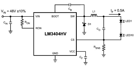
The LM3404 is a monolithic switching regulator that can be utilized to design a simple constant current driver for high-power LEDs. This LED driver project is suitable for automotive, industrial, and general lighting applications. Hysteretic control of the on-time,...
DC fan control circuit for a power amplifier. It features a variable speed DC fan that operates based on the input signal. The speed of the fan's rotation is dependent on the amplitude of the input signal received from...
This antenna selector circuit diagram utilizes PIN diodes, which address the drawbacks of mechanical switches, particularly in high-frequency current applications. PIN diodes are well-suited for this purpose due to their linear resistance characteristics across a wide range of current...
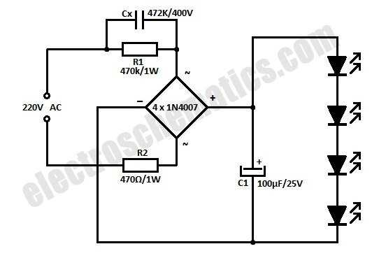
This is a simplified version of a white LED lamp that can be powered directly from the mains. It provides sufficient illumination for reading purposes. Capacitor Cx along... The circuit for the white LED lamp consists of several key components...
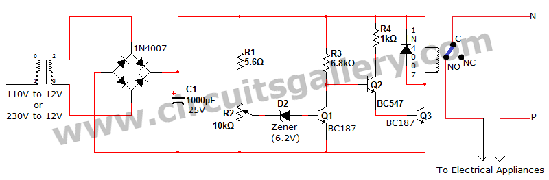
Voltage fluctuation is a significant concern in residential settings. For various reasons, the supply voltage may exceed 110V or 230V. This excessive voltage can potentially damage household electrical devices. An effective solution for electrical protection is the implementation of...
This circuit, based on the NE555 timer, activates and deactivates the IC output using a momentary switch. It functions similarly to a mechanical latching relay, but resets to its initial state when the power supply is turned off. This...
Warning: include(partials/cookie-banner.php): Failed to open stream: Permission denied in /var/www/html/nextgr/view-circuit.php on line 713
Warning: include(): Failed opening 'partials/cookie-banner.php' for inclusion (include_path='.:/usr/share/php') in /var/www/html/nextgr/view-circuit.php on line 713