
555 Momentary Switch Circuit
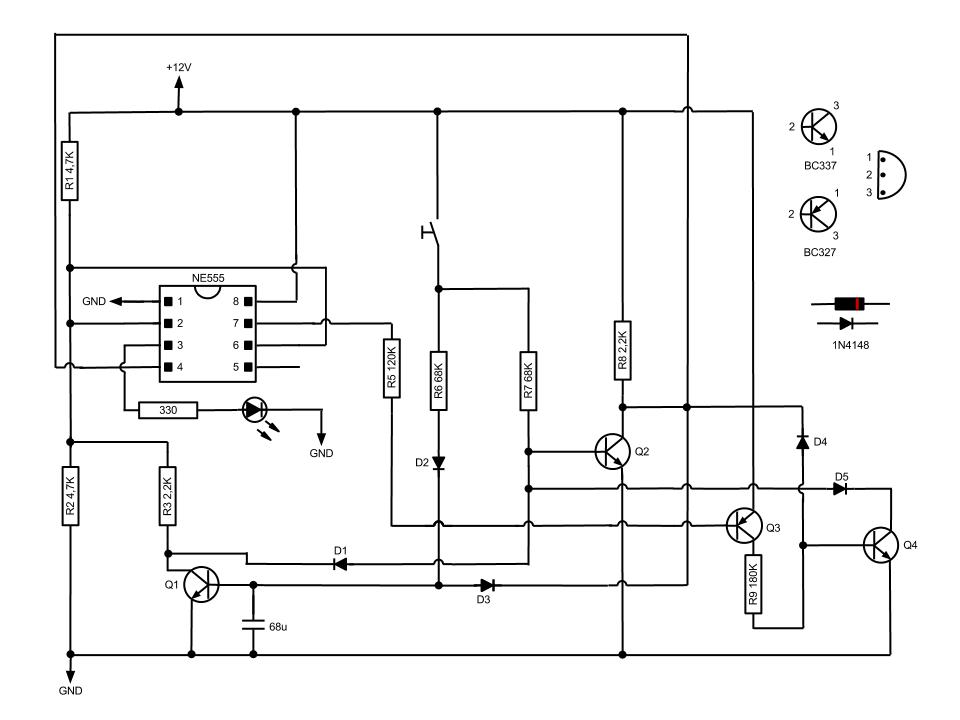
The NE555 timer is configured in a bistable mode, allowing it to function as a flip-flop. In this configuration, the momentary switch serves as a trigger to toggle the state of the output. The circuit comprises two transistors (Q1 and Q2), a capacitor, and a pull-up resistor, which work together to create a latching effect without the need for mechanical relays.
When the momentary switch is initially pressed, the capacitor charges quickly, causing Q1 to turn on. This action pulls the voltage at pins 2 and 6 down, which in turn causes the output at pin 3 to go high, illuminating the LED. The high output state remains until the switch is pressed again. Upon the second press, Q2 is activated, which pulls pin 4 low, effectively resetting the circuit to its original state and turning off the LED.
The design is particularly suitable for applications where a temporary activation is required, such as in automotive lighting systems, where the driver may want to activate a light briefly without maintaining the switch in the on position. The absence of mechanical components not only reduces wear and tear but also allows for a more compact and reliable circuit design. The use of a pull-up resistor is critical as it ensures that pin 4 is held high when Q2 is off, preventing any unintended toggling of the output state. The overall simplicity and effectiveness of this circuit make it a valuable solution for various electronic applications.Based on NE555 this circuit turns on and off the IC output by a momentary switch. In other words it works as a mechanical latching relay, but the circuit backs to the start condition when you switch off the power supply. This feature is often required in automotive devices. No relay contacts are used, infact I connected the output to a led. Once t he momentary switch circuit is supplied the output (pin 3) keeps off because pin 2 and 6 are at half voltage. When the button is pressed Q1 turns on within a fraction of second because of the capacitor, while Q2 keeps off.
By switching on Q1 leads pin 2 and 6 to low voltage, then the output gets high. When the button is pressed again Q2 switches on and leads pin 4 to low voltage (I used a pull up resistor), then the circuit takes the start condition. 🔗 External reference
Related Circuits
The EUA2032 is a high-efficiency, 2.5W mono class-D audio power amplifier. A newly developed filterless PWM modulation architecture further reduces EMI and THD+N, as well as eliminates the LC output filter, thereby reducing the external component count, system cost,...
The circuit is designed to power a CCTV camera, provide lighting inside a nestbox, and charge batteries using a photovoltaic (PV) solar panel. It includes a circuit diagram for a solar-powered wireless CCTV camera with battery backup. D1 is...
Operating at approximately 1.1 GHz, the detector senses disturbances in the electromagnetic field surrounding the antenna. The Doppler signal generated by detector D1 is amplified and used to control a power MOSFET switch. The antenna consists of a short...
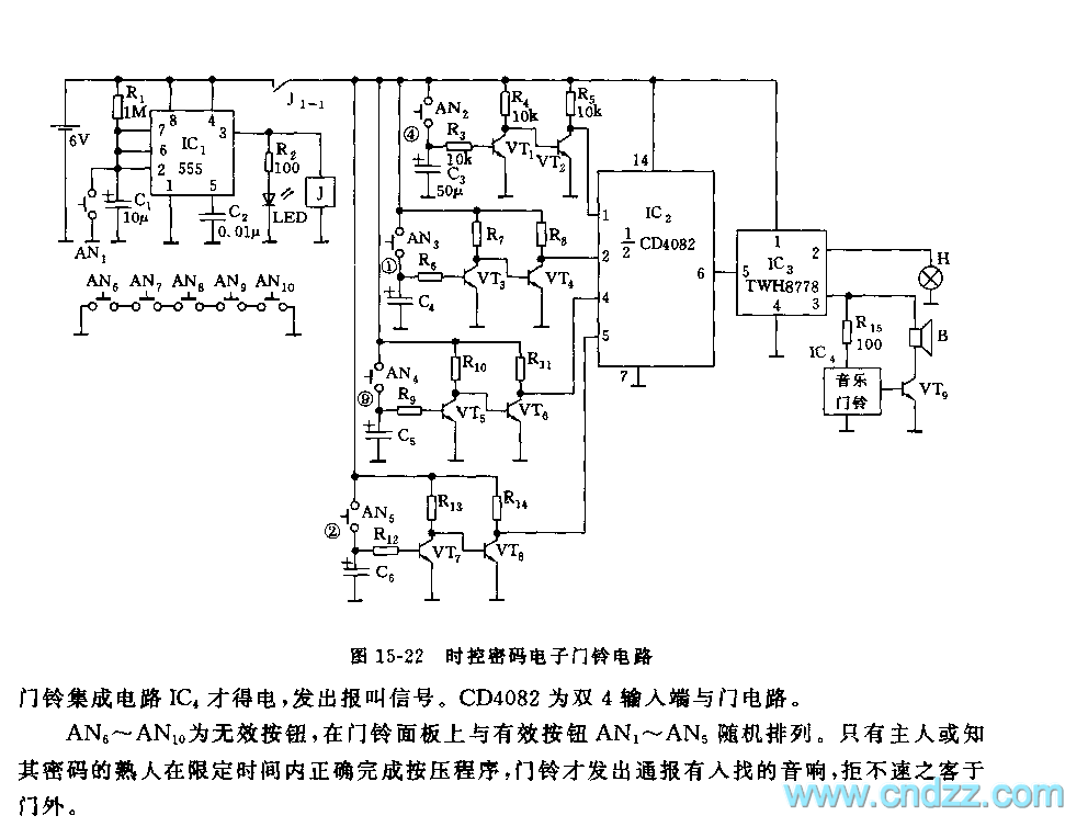
Figure 15-22 illustrates a doorbell system that consists of a monostable timing circuit, a password switch, a NAND gate circuit, and a sound output circuit. The operation of the circuit is designed such that when the password switch is...
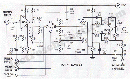
The first half of the circuit (IC1a) features an input sensitivity of 3 mV and includes a frequency correction network consisting of capacitors C5, C3, and resistors R6 and R8. The bass signal from the phono input is amplified,...
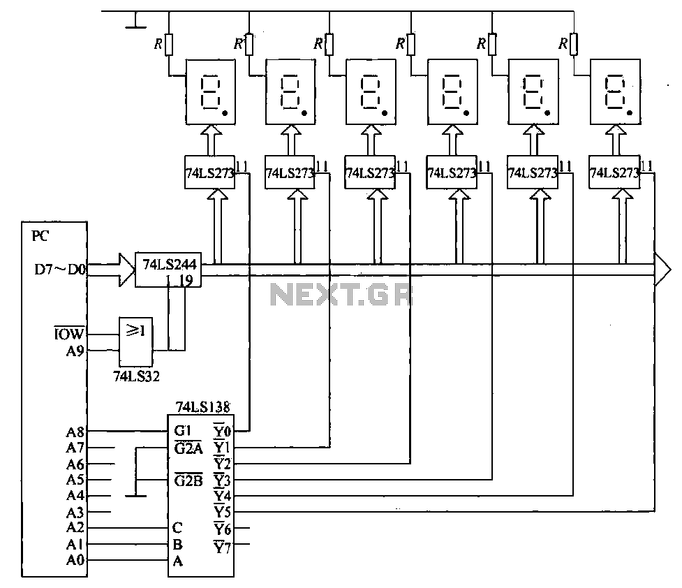
The static display circuit is illustrated in Figure 6. The 74LS244 acts as bus drivers, and six figures represent a public bus, each equipped with an LED display latch (like the 74LS273) connected to the code for latching the...
Warning: include(partials/cookie-banner.php): Failed to open stream: Permission denied in /var/www/html/nextgr/view-circuit.php on line 713
Warning: include(): Failed opening 'partials/cookie-banner.php' for inclusion (include_path='.:/usr/share/php') in /var/www/html/nextgr/view-circuit.php on line 713