
Simple Over Voltage Protection Circuit: High Voltage Cut Off
The over-voltage protection circuit utilizes a Zener diode to regulate voltage levels, ensuring that the output voltage remains within safe limits for connected devices. The Zener diode operates in reverse bias, allowing it to maintain a constant voltage across its terminals when the input voltage exceeds the specified threshold. This characteristic is crucial for preventing damage to sensitive electronic components.
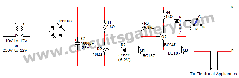
The circuit typically includes a relay, which acts as a switch to control the power supply to the connected devices. The relay is energized when the input voltage is within acceptable limits, allowing current to flow to the load. However, if the input voltage rises above the predetermined level, the Zener diode conducts, triggering the relay driver (Q3) to turn off. This action deactivates the relay, cutting off the power supply and protecting the devices from potential damage due to excessive voltage.
In addition to the Zener diode and relay, the circuit may include additional components such as resistors and capacitors to stabilize operation and filter out noise. The design can be tailored to accommodate various voltage levels and load requirements, making it versatile for different applications. Overall, this over-voltage protection circuit is a practical solution for enhancing the safety and longevity of electrical appliances in residential environments.Voltage fluctuation is a serious issue in every home. Due to some reasons our supply voltage may rise above 110V or 230V. Flow of this high electricity may lead to the damage of our home electrical devices. Have you thought how electrical protection is possible via a simple over voltage protection circuit Here CG comes with an interesting over vo ltage protection device to protect your electrical appliances from getting damaged. Zener diode voltage regulator is the main part of this high voltage cut off circuit. You can implement this over voltage protection relay circuit in your home as a high voltage regulator. Q3 is our relay driver, turning OFF of Q3 shuts down the relay too. When relay is OFF, there will be no supply of electricity to the device. Hence they are protected from over voltage. 🔗 External reference
Related Circuits
This circuit triggers an alarm when its LDR (Light Dependent Resistor) sensor is exposed to light from the sun or a lamp. A 555 astable multivibrator is utilized to generate a tone of approximately 1 kHz upon detecting light....
The control voltage is fed into the first half of a 1458 op-amp, this stage inverts the signal and sets the offset and gain for the right channel gain control circuit. This signal is then fed into the second...
The preamplifier is safeguarded against excessive input signals of either polarity by utilizing the 2N5909 junction field-effect transistor. A nulling circuit allows for the adjustment of the preamplifier output voltage to zero at a fixed low level (up to...
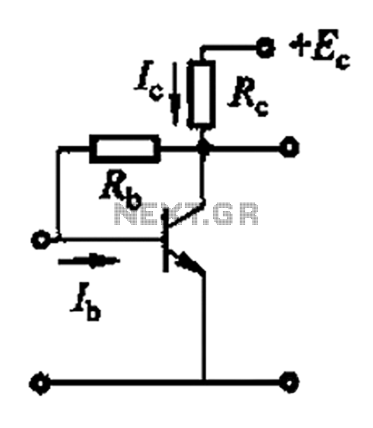
Basic reference bias circuit using a transistor with negative voltage feedback. The basic reference bias circuit utilizing a transistor with negative voltage feedback is designed to provide a stable output voltage or current that is largely independent of variations in...
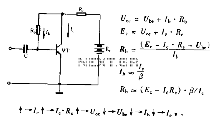
Bias voltage negative feedback circuit The bias voltage negative feedback circuit is a crucial component in various electronic applications, particularly in amplifiers and oscillators. This circuit is designed to stabilize the operating point of a transistor or operational amplifier by...
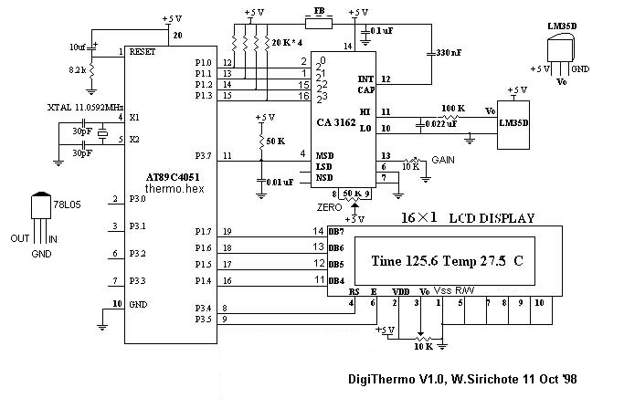
The A/D converter utilizes a dual-slope integrator to achieve a sampling rate of 10 Hz. The digital output sent to the microcontroller (MCU) is multiplexed in a four-bit Binary-Coded Decimal (BCD) format, starting from the Most Significant Digit (MSD),...
Warning: include(partials/cookie-banner.php): Failed to open stream: Permission denied in /var/www/html/nextgr/view-circuit.php on line 713
Warning: include(): Failed opening 'partials/cookie-banner.php' for inclusion (include_path='.:/usr/share/php') in /var/www/html/nextgr/view-circuit.php on line 713