
East Shi IDS-2000F STB switching power supply circuit
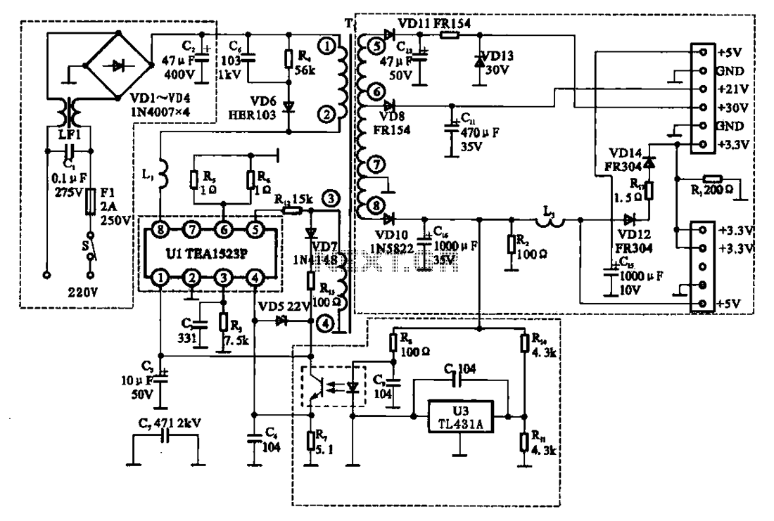
The East Shi IDS-2000F STB switching power supply circuit is a well-structured design that efficiently manages power conversion and regulation. The AC input circuit serves as the initial stage, where the AC voltage is filtered and converted to a high DC voltage. The inclusion of a fuse (F1) ensures protection against overloads, while the mutual inductance filter (C1) helps to eliminate high-frequency noise, enhancing the reliability of the power supply.
The switching oscillation circuit, utilizing the TEA1523P integrated circuit, is critical for maintaining the desired operational efficiency. This component generates the necessary switching signals to drive the transformer (T1), thus enabling the conversion of high-voltage DC into the required lower voltage outputs. The feedback mechanism, facilitated by the positive feedback winding, ensures that the oscillation frequency remains stable and responsive to load variations.
In the secondary output circuit, the multiple output voltages are achieved through the use of a switching transformer. Each output is rectified to provide stable voltage levels suitable for various applications, such as powering digital circuits, microcontrollers, and other electronic devices. The design incorporates voltage regulation to maintain output stability despite fluctuations in load or input voltage.
The voltage regulator circuit plays a vital role in ensuring that the +5V output remains consistent. The voltage divider formed by resistors R14 and R11 sets a reference level for the error amplifier (U3), which monitors the output voltage. Any deviation from the set point generates an error signal that is fed back to the TEA1523P (U1) via photoelectric coupling. This feedback loop allows for real-time adjustments to the oscillation output, ensuring that the power supply operates within specified voltage limits.
Overall, the East Shi IDS-2000F STB switching power supply circuit exemplifies an efficient and robust design, capable of delivering multiple output voltages with high reliability and stability.East Shi IDS-2000F STB switching power supply circuit East Shi IDS -2000F STB switching power supply circuit mainly by the AC input circuit, switching oscillation circuit, outp ut circuit and a secondary steady pressure control circuit and the like, as shown in Figure 2. 63. (1) AC input circuit AC input circuit is a switch S, fuse Fl, mutual inductance filter cl, LF1 and bridge rectifier circuit (VDI-VD4) and the like, its function is to filter the AC 220V input voltage and interference rectifier into a DC voltage of 300V, C2 to the smoothing capacitor. (2) switch and oscillation control circuit switches and the oscillation control circuit are integrated in Ul TEA1523P among the 30V DC via the switch of the primary winding of the transformer Ti O ~ to Ul foot power switch is integrated in Ul among the positive feedback winding ~ feet U1 provides power and positive feedback voltage to Ul access switch oscillation state.
(3) secondary output circuit switching transformer Ti attack multiple sets of output level, the rectifier output +5 V, + 21 V, + 3V and +3.V voltages. (4) regulator circuit voltage regulator circuit connected to the output of + 5V, Rl4, R11 constitute a voltage divider circuit, U3 to error detection and error amplifier, it will error signal by the photoelectric coupling of feedback to Ul feet, of Ul oscillation output controlled.
Related Circuits
Inexpensive miniature transformers typically provide one or two secondary voltages, which are sufficient for generating a set of positive and negative supply voltages, as required for operational amplifier circuits. However, if an additional voltage higher than either of the...

This board layout was created using the SOIC version of a PIC16F627A without drawing the usual schematic first. Most of the part values are etched on the Layout. The SIP resistor packs I used are 10k ohm, some experimentation...
The Pulse Demodulator, as illustrated in the accompanying image, consists of a CMOS Hex Inverter. This circuit is capable of performing envelope detection on amplitude pulses. The Pulse Demodulator utilizing a CMOS Hex Inverter is designed to extract the envelope...
This circuit is designed to detect whether the load of a battery charger or plug-in adapter is properly connected. The load may consist of a set of batteries needing charging or any other device that operates on low DC...
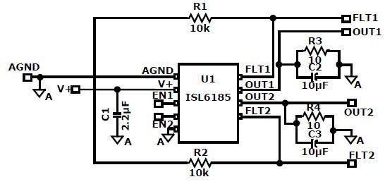
The ISL6185 USB power controller family can be utilized to design a straightforward USB power supply electronic project that offers fully independent overcurrent (OC) fault protection for two or more USB ports. This product family includes sixteen distinct functional...
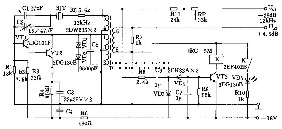
The circuit depicted is a 12 kHz intermediate frequency oscillator designed for an alarm system. It employs a variable feedback oscillation circuit where the oscillation frequency is primarily determined by a quartz crystal. Capacitors C1 and C2 are used...