
Pulse DemodulatorCircuit
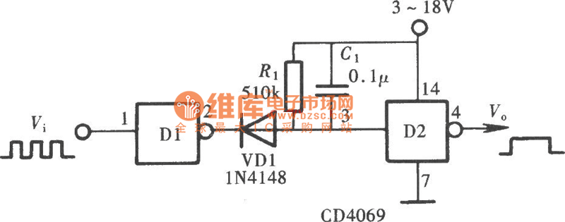
The Pulse Demodulator utilizing a CMOS Hex Inverter is designed to extract the envelope of amplitude-modulated signals. The hex inverter configuration allows for multiple signal processing paths within a single integrated circuit, enhancing the efficiency and compactness of the design.
In operation, the incoming amplitude-modulated signal is fed into one of the inverter inputs. The CMOS technology ensures low power consumption and high noise immunity, making it suitable for various applications where precision and reliability are critical. The inverter effectively inverts the input signal, producing a square wave that represents the envelope of the original amplitude-modulated signal.
The output from the inverter can be further processed by additional filtering stages to smooth the signal and retrieve the original modulation information. Capacitors and resistors may be employed in conjunction with the inverter to establish time constants that define the response time of the envelope detection.
This Pulse Demodulator circuit finds applications in communications systems, where it can be used for demodulating signals in radio frequency transmissions, as well as in various signal processing tasks requiring envelope detection. The versatility of the CMOS Hex Inverter makes it an essential component in modern electronic designs focused on signal integrity and efficiency.As is shown in the picture, the Pulse Demodulator is composed by CMOS Hex Inverter. This circuit can be used to process envelop detection on Amplitude Pulse.. 🔗 External reference
Related Circuits
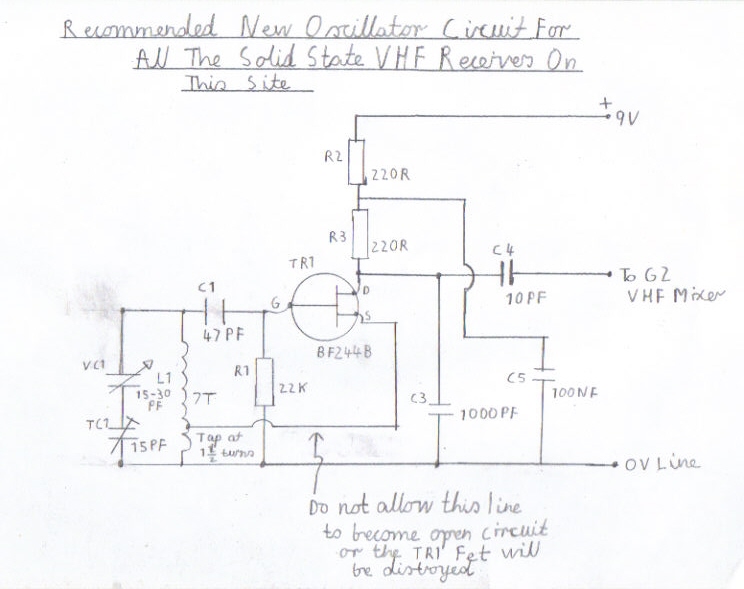
This section of the site provides construction details for a transistor VHF radio that was built using circuits as the foundational elements, compiled from various old radio magazines and books. Although the site is primarily focused on valve radios,...
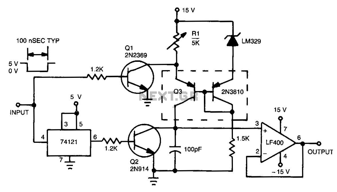
This circuit functions by charging a small capacitor using a constant-current source when a measurable pulse is present. The dual PNP transistor Q3 acts as the current source, with its output current determined by dividing the LM329 reference voltage...
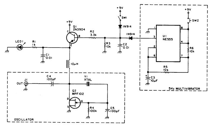
A marker oscillator can be constructed using an NE555 timer to generate pulses at an audio frequency. This design facilitates the identification of signals amidst interference. The oscillator can utilize a crystal with a frequency ranging from 1 to...

This indicator senses the switching on and off of the 48-V DC line voltage and transmits the pulses to logic circuitry. An Hl1A10 threshold coupler, with capacitor filtering, creates a straightforward circuit that can provide dial pulse indication while...
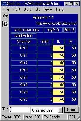
PulsePar turns a PC into a multi-channel pulse generator utilizing the parallel port. The period, duty and phase of each channel are adjustable so as to be used in PWM systems as well as in testing servo and stepper...
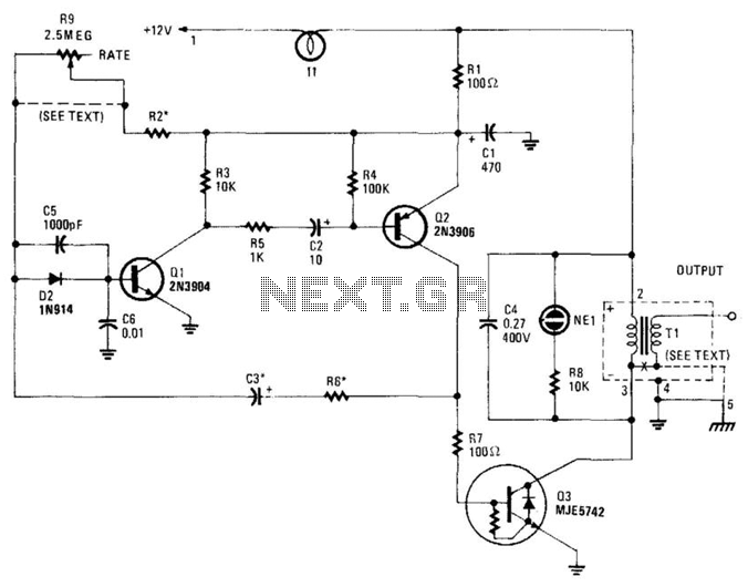
This high-voltage pulse supply generates pulses up to 30 kV. Q1 and Q2 form a multivibrator in conjunction with peripheral components R1 through R6, and C1, C2, C3, C5, C6, and D2. R9 adjusts the pulse repetition rate, while...